This thread has been locked.

If you have a related question, please click the "Ask a related question" button in the top right corner. The newly created question will be automatically linked to this question.

LM5017: Determining maximum ripple resistor

Part Number: LM5017

Hello,

I'm working on an LM5017 design, and I wanted to verify my understanding of the datasheet calculations.

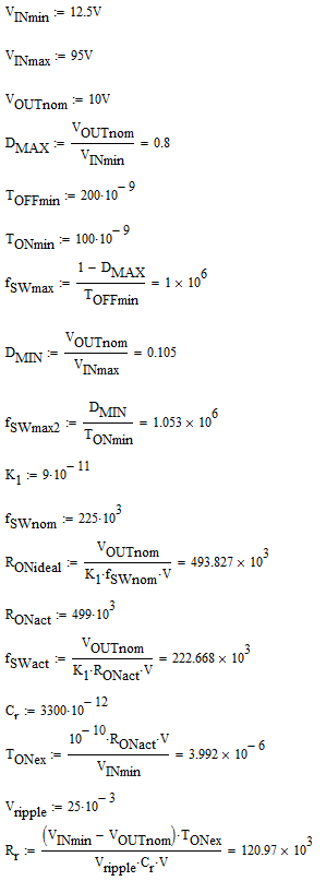
Equation 16 in the first application example (page 17) states that the maximum ripple resistor is calculated to be 57.6 kohm. However, when using the values provided earlier in the example, I come up with 121 kohm:

When using the LM5017-QUICKSTART-CALC and the application example's conditions (VINmin = 12.5V), I get 134.99 kohm, but I can't see the equation for the locked cell (F53), so I'm not sure how that is being generated either.

Can you help me understand where 57.6 kohm in the datasheet comes from, how the quickstart calculator comes out to 135 kohm, and which one is right?

Thanks,

Jonathan

  • Hi Jonathan,

    My understanding is that it's the same equation, just a different target ripple voltage spec or input voltage condition. The larger resistor will provide a lower ripple amplitude at FB, and you should verify circuit operation and stability at minimum input voltage (lowest ripple operating point).

    Regards,
    Tim
  • Hi Tim,

    Thanks for the reply. Could you provide the password to unlock the calculator (either here or offline)?

    The datasheet equation specifies 25 mV in equation 16, and my calculations use the same VIN, so the only difference must be in the T_ON(VINMIN) parameter. Looking at Figure 5, a TON of ~4 us seems reasonable for RON = 499 kohm and VIN = 12.5V:

    I need to establish the best reference for calculating these values, so if we can clear up how the datasheet comes to 57.6 kohm, and know what's behind the equations in the calculator, that will help immensely. Once I can make sense of the outputs and have some confidence in them, I can populate the board with those values and verify.

    Thanks,

    Jonathan

  • Hi Tim,

    Sorry for the double post. I cracked the spreadsheet calculator, and found a few inconsistencies between the datasheet and the calculator's constants:

    Note the minimum on time is 125 ns instead of 100 ns, and K = 1*10^-10 instead of 9*10^-11.

    Do you know which value should be used - 100/125 ns, 1*10^-10/9*10^-11?

    Thanks,

    Jonathan

  • Hi Jonathan,

    I will confirm. In the meantime, take the datasheet parameters for Ton-min and K as correct.
  • Thanks Tim. I emailed you the unlocked Excel offline in case you needed access.

    I also noticed VREF in the constants table of the spreadsheet is 1.25V, when the datasheet parametric table shows it's 1.225V. Is 1.25V used assuming a 25 mV offset due to the ripple injection? The application section wavers a bit on this point as well - section 8.2.1.2.2 shows the equation for the feedback resistor divider, and states VREF = 1.225V, but the 7:1 ratio given would be for VREF = 1.25V.

    Thanks for your help in dissecting the datasheet and calculator to help me understand the LM5017 design process.

    Jonathan
  • Hi Jonathan,

    1.225V is the reference voltage. Min amd max are provided in the datasheet EC table as 1.2V and 1.25V, respectively.

    Regards
    Tim
  • Hi Jonathan,

    Please click on Resolved if there are no further questions so we can close out this thread.

    Regards,
    Tim

  • Hi Tim,

    I need a bit more time with the EVM to check the stability and VOUT regulation with a few different FB divider and ripple injection resistor values before I can call the questions closed.

    At first power-up, the VOUT was a bit low (3.282V at no load, 3.273V at 0.6A load), which would indicate that the 1.25V VREF value used in the spreadsheet calculator should perhaps be lowered a bit. If we assume 25 mVpp is injected from the DCR circuit, and add half of that to the 1.225V VREF, we get 1.2375V. Changing the spreadsheet VREF to 1.2375V, the calculated VOUT for RFBB = 10 kohm, RFBT = 16.5 kohm, is 3.28V, which agrees with what I'm seeing on the bench. So I'll try RFBB = 10.7 kohm and RFBT = 17.8 kohm to see if that gives me the desired 3.3V nominal setpoint.

    If so, I'd recommend the calculator be updated on TI.com with the K value and minimum on-time to match the datasheet, and perhaps VREF and the resulting FB resistor calculator output to be changed, assuming it's related to using the Type 3 ripple injection circuit.

    I'll also take a look at the SW node at the VIN(min) and VIN(nom) across a few load conditions, with both the 150 kohm Rr pulled from the calculator, and a smaller value, to observe any changes and verify stability.

    Thanks,

    Jonathan