This thread has been locked.

If you have a related question, please click the "Ask a related question" button in the top right corner. The newly created question will be automatically linked to this question.

UCC27524: Inquiry

Part Number: UCC27524

Hi Team,

One of my customers is facing issues with our part and have the below questions:

We are currently using this to drive four (4) MOSFETs in a Full Bridge Topology using a Gate Drive TRF for isolation.

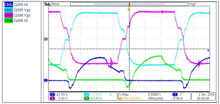
However, we are having random/intermittent unexplained failures for the FET and the driver.

I would like to inquire if the output of this driver is capable of bi-directional currents?

I understand the output section of the driver IC is MOSFET based.

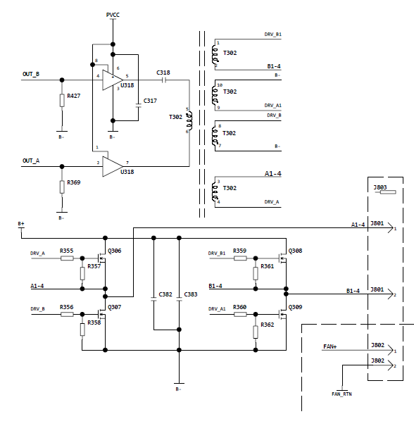
With our current gate driving circuit, we expect current to source out of the OUT pin with the OUT pin voltage low.

Thanks!

Best Regards,
Alfred Logico

  • Hi Alfred,

    Thanks for reaching out and explaining whats going on.

    This topology is a quadruple ended transformer gate drive for a full bridge. Typically theres a double ended transformer driving each complementary pair of signals on each leg of the full bridge. This is to implement a deadtime to prevent cross conduction. Its possible that since there is no deadtime considerations the shoot through is leading to the FETs/driver damage, can you confirm this?

    A deadtime can be implemented by sizing gate resistors for slower turn on and a fast turn off circuit to facilitate non overlap in the complementary signals. You can check out www.ti.com/.../slua618.pdf section 7.2 and section 3.4 to read more about this.

    Can you show me gate drive signals for one leg so we can see if the signals have any overlap?

    Thanks,
  • Can you further explain why you expect current to source out of the OUT pin with the OUT pin voltage low?
  • Hi Jeffrey,

    Thanks for the response!

    See waveform below:


    Waveform is for one leg of the FB. There are no shoot-through currents seen.

    The deadtime is set by the duty cycle on the input PWM of the driver IC. The current design is at 44% DC at 140KHz switching frequency.


    We were also looking into slua618 and noted at page40:

    “Therefore, the output must handle bi-directional current with transformer coupled gate drives.”

    This prompted the query on UCC27524 IC and its capability of handling bi-directional current.

    We also included negative catch diodes in our design (similar to what is mentioned at slua618); however, when measured we still see most current flowing through the IC OUT pin as return path.


    Going back, does that mean the UCC27524 is capable of handling bi-directional current?

    Thanks!

    Best Regards,

    Alfred Logico

  • Hi Alfred,

    Thanks for the update! Thanks for checking out slua618, its a great app note with tons of info. UCC27524 is capable of bidirectional current or current that is opposite the direction of the state of the driver. This is possible because of a MOSFET output structure and not bipolar. So during the low state of the driver there can be both current directions through the lowside of the output structure.

    There looks to be a small bit of shoot through current at the end of the Id cycle which happens right when the complimentary transition happens, does the intermittent issue go away with more uC PWM deadtime? Its also possible that the output is seeing some negative voltage. The output is only capable of -2V for 200ns. To check this probe the outputs (pin 7,5) wrt IC ground (pin 3).

    Thanks,