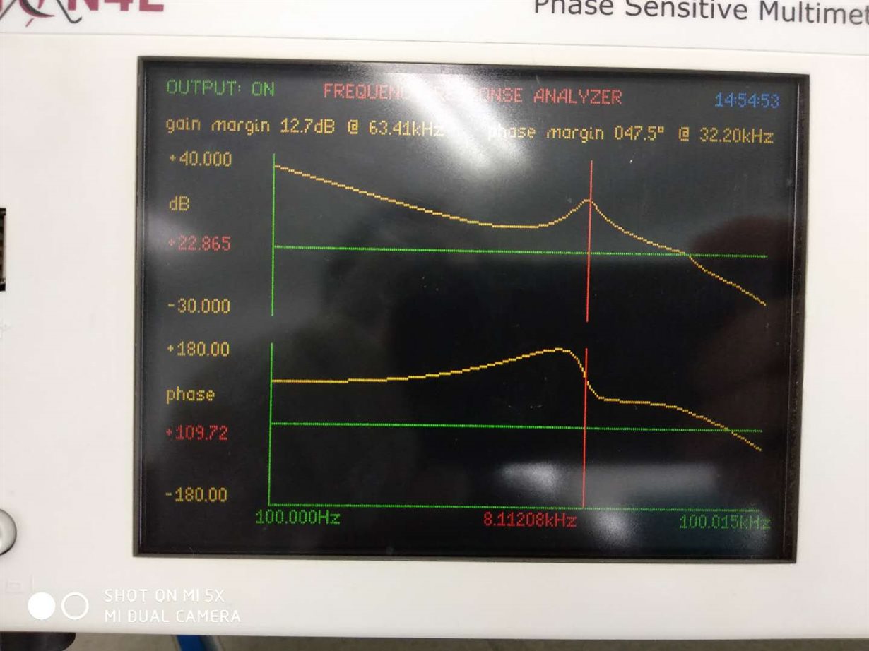
Hello, I imitated the LM5035 half-bridge demo board to make a 300kHz switching frequency 5V/10A power supply.
When I was doing a 5A-10A-5A load step experiment, I found that the step size was relatively large, about 240mV at room temperature, and about 400mV at high temperature.I want to lower the step amplitude to 350mV.
I tested the Bode plot of the power supply at room temperature. The crossover frequency is about 30kHz, the phase margin is about 45 degrees, and the output capacitance is 80uF. I refer to the formula 128 in the slup340 "Switch-mode power converter compensation made easy" provided by the TI Power Technology Symposium: Vp=(I1-I2)/(8*fc*Cout)=5A/(8*30kHz) *80uF) = 260mV, which is very close to the 240mV I measured at room temperature.
But I don't know why the load jump will increase to 400mV at 85 degrees, which I don't want. According to the formula, I increased the Cout to 160uF. However, the load jump amplitude did not decrease as expected. In general, it only decreased to 380mV at high temperatures, with little success.
may I know what is the reason? Why does the load jump amplitude increase a lot at high temperatures? Why only increase the output capacitor value, at high temperatures, the load jump can not be a linear drop it? At high temperatures, does the crossover frequency decrease? How can I reduce the load jump further? I hope that at high temperatures, it can be reduced to 350mV or even lower.
Looking forward to your advice


