


Hi
First Question. The LM5170EVM-BIDIR has several pins for jumper insertion or power supply.
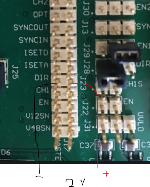
When voltage is applied to these pins, how should the + - terminal be connected?
For example, when applying voltage to J17 # 9 (DIR), there are two pins.
Do you connect + and - to each of these two pins to supply the voltage?
Second Question

Each pin in the illustration has a white portion and a gray portion.
In addition, the user's manual indicates 1, 2 or 2 or 3 when configuring jumpers.
Where is it once?
Is it the first gray part?
I would appreciate your reply.
