This thread has been locked.

If you have a related question, please click the "Ask a related question" button in the top right corner. The newly created question will be automatically linked to this question.

BQ25606: Unstable power with TPS63070 after plugging USB to BQ25606

Part Number: BQ25606
Other Parts Discussed in Thread: TPS63070,

Hi,

We are currently testing a prototype and have some problems with the USB charger.

At first, everything seemed perfect, the batteries were charging with USB and the PCB was operating on battery power. But one time, we plugged the USB for 20 minutes (to recharge the batteries), unplugged it when we found that the battery connector was hot, and since then, the PCB does not work.

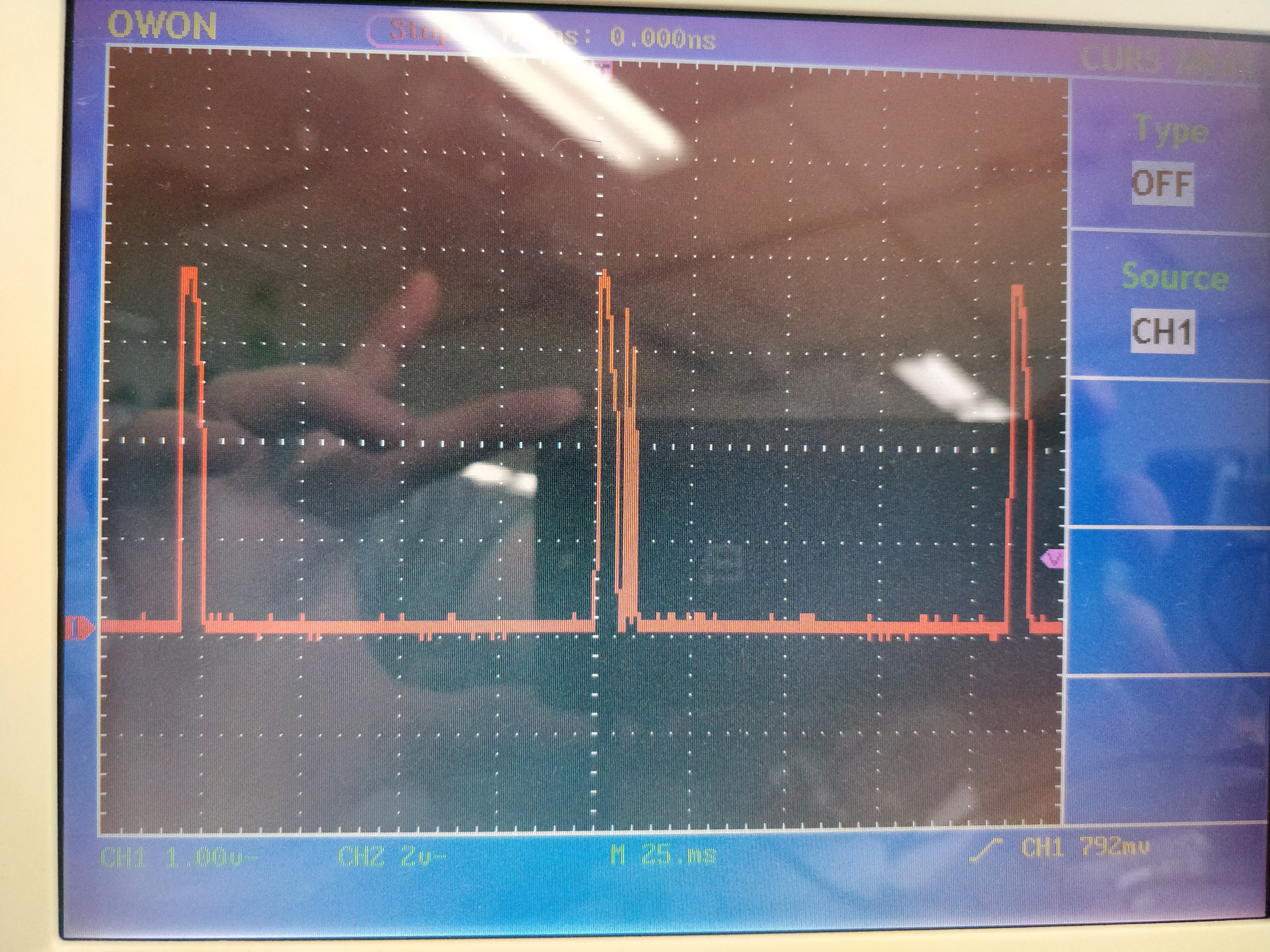
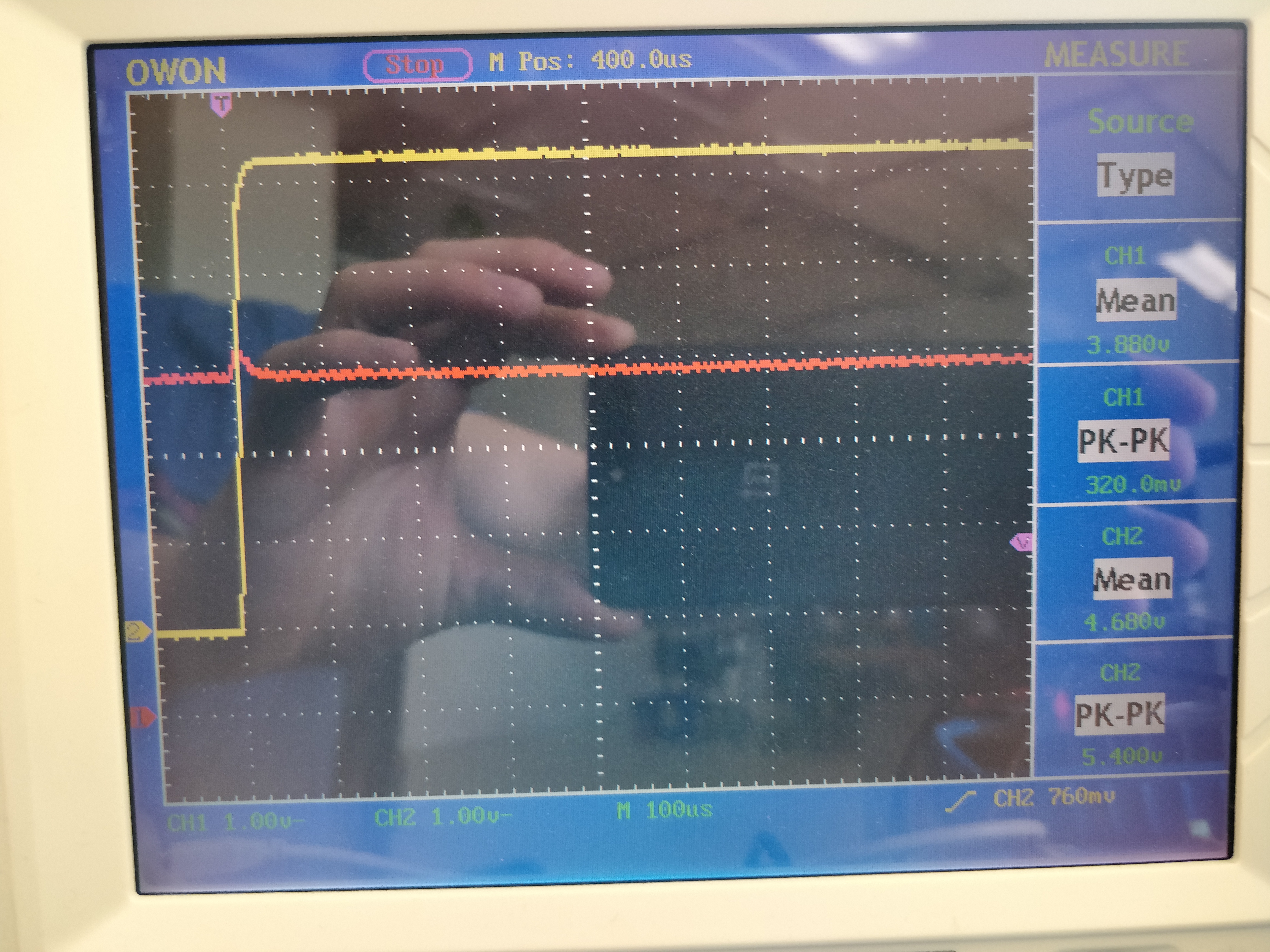
We plugged a power supply at 4V instead of batteries at +VBAT/-VBAT, and the power supply's display toggled constantly between 0 and 4V. I checked the output of the charger on a scope and it looks like the charger tries to start, fails, then tries again 100ms later (I will try to attach a picture). Again, this PCB worked really well before the problem.

This is the second PCB to have this problem appear after charging through USB. What can we do to debug the source of the problem?

Thank you,

Fred

  • Here is a picture of the charger's output when connected to a power supply at 4V.

  • I've cut the trace that connected V_CHARGER_OUT to our buck/boost's input (TPS63070), and connected our power supply directly to the TPS63070, and there was clearly a short. I reapplied 4V at the input of the charger and its output was a clean 4V also, so the charger seems to be doing its job (going in overcurrent protection).

    I now need to debug why our TPS63070 failed. Should I change the forum of this discussion (if it's possible)?
  • Yes, you should change the title to reflect TPS63070 so related TI experts can help you.
  • It seems that the problem was finally the BQ25606.

    We found that there was a short of 7.5 Ohms between SYS and GND. Note that the SYS pin is connected to VIN of the TPS63070.

    I unsoldered the TPS63070 from the circuit and I still had the short.
    I unsoldered every decoupling capacitor on the SYS line and still had the short.
    I unsoldered the inductor between SYS and SW, and the short disappeared, but the short was now between SW and GND.
    I unsoldered the 47 nF between SW and BTST, and the short was definitely between SW and GND.
    I unsoldered the BQ25606 and the short disappeared.

    Looking at the datasheet, that would mean that the internal LSFET Q3 is shorted to PGND.

    We've had 3 boards with this problem now, one which had the problem happen without even connecting the USB. For that specific board, the short is 2 Ohms instead of 7.5.

    What could be the cause of this? We used the recommended circuit in the datasheets (BQ25606 and TPS63070).

    P.S.: We have a 5.5V TVS diode on VBUS.

  • I've just noticed that the datasheet says that the OTG pin musn't be left floating, which is what we did on our PCB. What sort of problems could this do? Should I connect it to GND if we don't use USB OTG?
  • Hello,

    In regards to the OTG pin floating, the main issue is that the undefined state of the pin could trigger force the part into OTG mode accidentally.

    However, what I am most curious about is the initial test conditions that prompted the device short.

    You stated that at one point, you applied a USB source for 20min, came back, and the IC was hot presumably due to the short. Do you have details about the battery voltage at that point?

    More importantly, I would like to see a startup waveform of your product showing the SYS voltage, VBUS voltage, SW voltage waveform, and perhaps either the SYS current or the VBUS current. This could help identify any issues at startup. It would also be beneficial to see those same waveforms on the charger, but when the TPS63070 is present or when it turns on.


    Regards,
    Joel H
  • BQ25606 is high voltage device operating up to 13.5V input. Q3 voltage damage is unlikely. Do you think it is solding short?

    OTG should be tied to GNG when not used.

    Can you check if SW and GND are short on the taken out IC?
  • Hi,

    I don't think it's a solder short as two of the PCBs were fine before the USB problem. Also, the short is 2-7 Ohms instead of 0 Ohm.

    I will ground the OTG pin.

    The taken out IC is actually destroyed, I wasn't able to unsolder the ground pad.

  • For the PCB that failed without plugging the USB, we only applied 4V at +VBAT/-VBAT using an external power supply. Then we saw that the voltage on the power supply was going wild, so we stopped using that PCB.

    For the PCB that failed after 20 minutes:

    We have 5 LEDs that indicate the approximate state of charge of the battery (0-20%, 21-40%, 41-60%, 61-80%, 80-100%). The batteries were at the 4th LED (61-80%) before plugging the USB. After 20 minutes of USB charging, the 5 LEDs were on (80-100%). After unplugging the USB, only 2 LEDs remained on (21-40%), but that also means that the microcontroller was still operating (the LEDs are controlled via firmware). We then unplugged the batteries, and observed that the connector was hot. After that, we plugged an external power supply instead of batteries and we observed that something was shorting the power supply (the voltage display on the power supply was oscillating). It was found yesterday that it's because the charger's Q3 failed.

    For the curves that you wanted, I got two:

    1 - 100 us/div; Channel 1 (red) = V_SYS, 1 V/div, Channel 2 (yellow) = VBUS on a USB connection, 1 V/div

    2 - 100 us/div; Channel 1 (red) = VBUS current (on a 0.12 Ohm Rsense), 200 mV/div, Channel 2 (yellow) VBUS on a USB connection, 1 V/div

    On the first curve, you can see that VSYS has a peak of ~320 mV when connecting the USB.

    On the second curve, you can see a surge of current when the USB is plugged. The Rsense is 120 mOhms, and the scale is 200 mV/division, which gives a peak current of 5.6 amps! Is this normal? Our ILIM resistor is 536 Ohms, which should give a current limit of 478/536 = 891 mA, and our ICHG resistor is 680 Ohms, which should give 677/680 = 996 mA.

    Now, there is an IC on the board which we only power when there is a USB connection detected, because it can consume quite a bit. For the curves above, I didn't power the IC. I then tried the same test but by powering the IC on a USB connection, and the charger failed again. Could the BQ25606 be burnt by the extra current required by the IC coupled with the sudden current rush on a USB connection? I don't have a curve for this test, as my scope did not trigger.

    Now, the details of what happened on that last test :

    1 - PCB is running normally, batteries are connected, the 5 LEDs are ON (80-100% state of charge)

    2 - USB is connected

    3 - Other IC is powered

    4 - The LED count drops to two (21-40%)

    5 - PCB is still running

    6 - Unplug the batteries, noticed that the connector was hot

    7 - Test for a short between SYS and GND, there was none

    8 - Wait a bit, then plug a power supply instead of batteries

    9 - The power supply's display is going crazy, PCB does not power up, unplug the power supply

    10 - Test for a short between SYS and GND, and there is now 4.5 Ohms between both.

    Hopefully this can help you diagnose my problem.

    Thank you and have a great day,

    Fred

  • Hey Fred,

    I was looking at your two waveforms, and I cannot see why there is a difference in the VBUS waveform. It looks like all you added between waveform 1 and 2 was a sense resistor, but for some reason VBUS has a small 400mV spike on the input voltage in waveform 2. Is there something else different between your two test setups?

    Secondly, are both waveforms taken on a non-damaged board? The second waveform looks to me like inrush current into the caps rather than the charger, but the pulse lasts quite a long time relative to the capacitances. 

    Additionally, looking at the SW node would be beneficial here to see if the charger is switching at all. 

    In regards to the LED indication of battery capacity: how is battery capacity determined? In other words, what measurement taken from the battery indicates the percentage? Are the LEDs in series or parallel?

    And for your last test, you mentioned the battery is @ 80% to 100% charged and the other IC is powered after the USB input is detected. How much current does this IC consume? Is it connected to the buck-boost device?

    Regards,

    Joel H

  • Hi Joel,

    I've sent you a private message