This thread has been locked.

If you have a related question, please click the "Ask a related question" button in the top right corner. The newly created question will be automatically linked to this question.

TPS92641: Input current

Part Number: TPS92641
Other Parts Discussed in Thread: CSD17510Q5A

Dear E2E member,

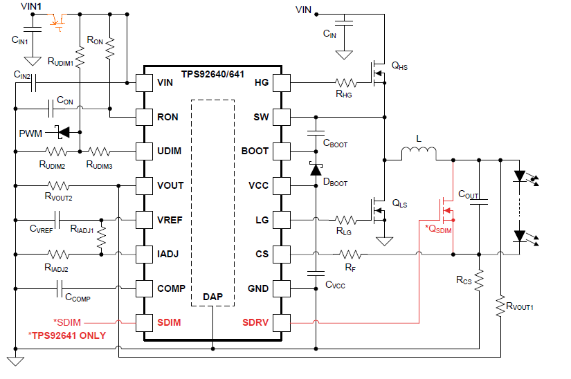
Our Customer use TPS92641 to design, and the circuit as below.

Because some green mode demand, they need to add a PMOS(Color:orange) in Vin1 side.

So, could you let us know how much current will through the PMOS?  Customer need to assess.

Thanks a lot.

  • Hello Julian,

    I need much more information:
    What is Vin?
    What are the MOSFETs used and what is the switching frequency?
    What is the shunt MOSFET and what is the switching frequency?
    What is Rudim1 and Ron

    Regards,
  • sorry, I update the circuirt,

    What is Vin? 16V→12V/5A
    What are the MOSFETs used and what is the switching frequency?

    MOSFET is BSS84(P-ch) and 2N7002(N-ch),


    What is the shunt MOSFET and what is the switching frequency?
    What is Rudim1 and Ron

    Does this 2 item will affect the Input current?

    Customer just want to know does the BSS84 (0.13A) is OK for this design.

  • Hello Julian,

    The current through Vin is a combination of the IC bias current and the gate drive of Qhs, Qls and Qsdim.  The Vin current for the MOSFET gate drive depends on the switching frequency, input voltage and MOSFETs chosen.  The BSS84 is probably okay but it would be good go check this especially if operating at high switching frequency.

    Regards,

  • Dear Irwin,

    The detail as below,

    What is Vin? 20V

     What are the MOSFETs used and what is the switching frequency? BSC019N04LS*2(Qhs),  BSC019N04LS*2(Qls) and switching frequency is 300KHz  

    What is the shunt MOSFET and what is the switching frequency? CSD17510Q5A*1(Qsdim) and dimming frequency is 1KHz

    What is Rudim1 and Ron? Rudim=1.5R, Ron(RHG,RLG)=3.3R


    So, is it OK for use BSS84 (0.13A) from input current?

    Or you can let us know the formula and I can calculate it!


    BTW, I also concern the power sequence, becasue the Vin1 always have power so UDIM is power ready before Vin(IC Vin) enable. 

    Is the power sequence OK for the circuit?

  • Hello,

    I have to clarify this:

    Is the input 16V and the output 12V at 5A?  Or is the input 20V?  I need to know the output current because this is a lot of MOSFET for a 5A design.  The bias current from the gate drive will be around 80 mA which will be over a watt of dissipation in the TPS92641.

    Ron is the resistor to the RON pin, it cannot be 1.5R

    Rudim1 goes to Rudim2 and Rudim3, it cannot be 3.3R, that value is for the gate resistors to the MOSFETs.

    I would move the disable MOSFET back to your original placement before Ron and Rudim1.

    Regards,

  • Dear Irwin,

    Sorry, I update newest condition to you.

    1. 20V→8V/5A

    2. RON = 51k

    3.They don't use Rudim2 and Rudim3, is it OK for design?

  • Hello Julian,

    I set OVP to about 10V and I get the switching frequency at about 200 KHz.  Rovp1 and Rovp2 are part of the switching frequency calculation.

    I would move the BSS84 connection so R303 and R304 are tied to the Vin of the TPS92641.  The current though these is less than 1 mA.

    It is okay not to use Rudim2 and Rudim3, however R305 is Rudim2 so it is being used.

    They need to run the loss calculations on the MOSFETs, switching and conduction, this seems to me this too much MOSFET for 5A.

    Regards,