This thread has been locked.

If you have a related question, please click the "Ask a related question" button in the top right corner. The newly created question will be automatically linked to this question.

UCC27537: UCC27537 EN-PIN Low Vol

Part Number: UCC27537

HI Sir:

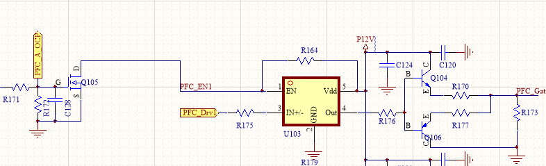
     pls  ref this Schematic diagram. the Pin EN should be 12V , But it's going to slow down. Finally about the 2 v. and remove the R164 and Q105.  it also 2V. I want to know why,  and R164 =47K. and the chip i used is  sample from TI. of course I  use new chip to replace the bad.  it's ok when i used. some time later it also be to 2V.

  • Hi Lei,

    Thanks for asking about ucc27537 I'm in apps engineer with this device and hope to help out.
    This issue seems to be happening in steady state and damaging the EN pin. Lets see what else is going on in the IC since floating the EN pin does not produce 5.8V internal pullup reference rather 2v. What value is r172?
    Is it possible for you to take a couple waveforms while things are properly switching? It will help to determine if the device is functioning properly.
    EN, IN, VDD, OUT (wrt GND)

    Thanks,
  • Hi sir :
    if the EN float. It should be 5.8V,but it will slow down to 1V.About the R172 ,I think Q105 just as a switch to enable and disable.the R172 should no effect on EN Pin
  • Hi Lei,

    Thanks for the update!

    So it starts as 5.8v then slowly goes down to 1v?  There may be a leakage path somewhere internal, this is unusual behavior for the EN pin, its possible you have damaged the part in another way. Are you able to take waveforms of the issue with a brand new part?

    How long after replacing the part does the issue manifest?

    Thanks,

  • Yes,it starts as 5.8v then slowly goes down to 1v. Now we remove Q105 and R164. the issue is still there.
  • Hello Lei,

    I am a TI applications engineer who works with Jeff, and will work to help understand the concerns. At this point, it is not clear what is causing the behavior you are describing. I want to ask a couple of questions, and ask you to try a couple of things, and take some waveforms.

    I want to clarify a couple of things in the conditions you describe. When the UCC27537 is a new part (before low EN voltage occurs). What is the voltage on the EN pin with R164 47K in place and Q105 turned off? I would expect this to be higher than 5.8V since there is a 47K external pull up to 12V and 500k internal pull up to 5.8V.

    When the EN voltage starts dropping as you describe, to ~2V does the enable/disable function still work? Or is there a condition where the enable function does not operate?

    With a UCC27537, with a fresh part, and all components installed. Can you get scope waveforms of IN+, EN, OUT and VDD with the condition of EN cycling on and off? Also can you record VDD during startup, power down, and various load conditions and confirm the voltage range (min and max) of VDD?

    Can you try a new part, and remove R164, and confirm if the EN voltage drops over time as you described before.

    Regards,

    Richard Herring

  • Hi Lei,

    Do you have an update on this issue? If not I will assume that we solved it.

    Thanks,
  • Ths .I will update but if I have a e-mail of you.it will help we to communicate the problem
  • Hi Lei,

    Thanks! Since there is no proprietary info, Its important that we keep this thread on e2e to allow others that may have a similar issue to stumble upon this thread. Sorry for this inconvenience. I will await your update!

    Thanks,

  • Hi jeff:
    We test a new part remove the R164 the EN-PIN is above 4V. if R164 is Keep in The EN_Pin is 12.4V. And Q105 is always keep off.
    And we have three identical circuits. No one is oK. The En pin is above 2V ,down 2V ,even to less than 1V. But then the en_pin is above the threshold.
    About scope waveforms it is difficult now.But about the 12V supply. It's limited to 12+-0.5V
  • Hi Lei,

    Sorry to hear you can get any waveforms, I will do my best to ask questions that will lead to a solution. First, to clear up some confusion I am going to sum up your post. Please let me know if I miss something:

    1) When R164 is removed and Q105 is always off, the enable stays high due to the internal pull-up and the circuit functions properly. When R164 is populated and Q105 is always off, the issue of EN slowly falling below the threshold occurs, is that correct?

    2) When the EN slowly goes below 1V, is VDD still a constant 12V?
    3) are you PWMing when the issue occurs?
    4a) what is the cap value the Vdd pin?
    4b)I also see some other nodes on the VDD pin clipped off the bottom of the circuit that might be affecting the 12V. Can you tell me what else is connected to the VDD pin?

    Thanks,
  • Let’s summarize this issue.
    1. We use a 47kohm resistor pulled up to 12V+/-0.5V(typ 12.4V), and NPN MOS to EN/DIS IC(Here,R171 not placed, so we can assume Q105 is always off) . When it is a new IC, the EN pin is correctly pulled up to about 12.4V. (no drive signal inserts)
    2. After we start our product and shutdown sometimes later (not clear when it happened), which means drive signal inserted and IC output enabled, we found the EN pin was lower than expect(it should be 12.4V, but may be observed 2V, 1.5V, 0.3V… ). The worst, when the voltage goes lower than threshold, there would be no output any more!
    3. We found this issue from failed IC as described above. Then we replace it with a new IC, it repeats some time later.
    4. Also, we tried remove the 47kohm(floating EN pin, 4.8V detect at first) or use smaller (10kohm) value, it doesn’t help.
    5. We have three same circuits with same power supply. Now each of them have occurred the similar problem.
    6. We say it is hard to observe with a scope because it is uncertain failure case and not in a one-time use. I agree with you that some damage may done to EN pin and I want know why and how.
  • Hi Lei,

    You can try to replace the drivers then start the system up so we can see what the waveforms are looking like with a working system.

    What is the application?

    How much later does the failure occur after replacing IC? only the 537 gate driver fails?

    Whats the impedance of EN->GND and EN->VDD after the units fail?

    Did you trying putting a bypass cap close to the enable pin to see if that helps the problem?

    Thanks,

  • Hi Lei,

    Since we haven't heard from you in a while, we must assume you solved this issue. It would be great if you could let the Community know what the issue was - it might help someone else with a similar issue.

    If your issue isn't closed, feel free to reply to this thread, and we will work with you to get it resolved.