Other Parts Discussed in Thread: BQ500210
Hello,
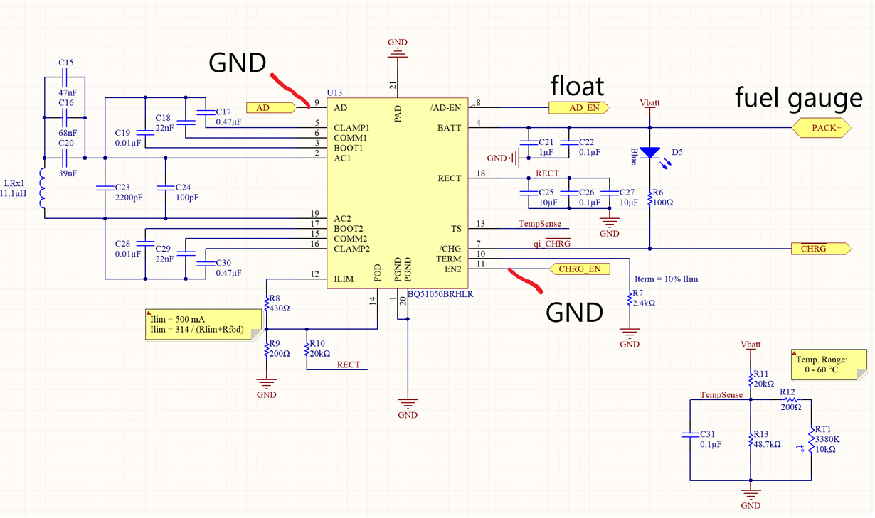
We designed a wireless charger (Rx) based on the reference design for the bq51050b as per schematic shown below
with coil TDK WR-483250-15M2-G , there is a fuel gauge in between the battery and the charger (bq27421).
On the Tx side we use a Logiix (QI)10W Fast charger as well as a UNITX-8610 (with no certfications) based on the bq500210. (We also have a POWERQI T-100 (5V, 1.5A) charger which we test occasionally with but also isn't communicating).
Testing using the setup as shown in the schematic was not successful, so we proceeded to modify the board to match the values in the reference design fully. C20 was updated to 68 nF, C23 to 1800 pF and R10 to 42.2k. This yielded better results as shown below but still failed to charge the battery, COMM caps were also increased from 22 nF to 47 nF with no noticeable differences (higher voltage peaks)
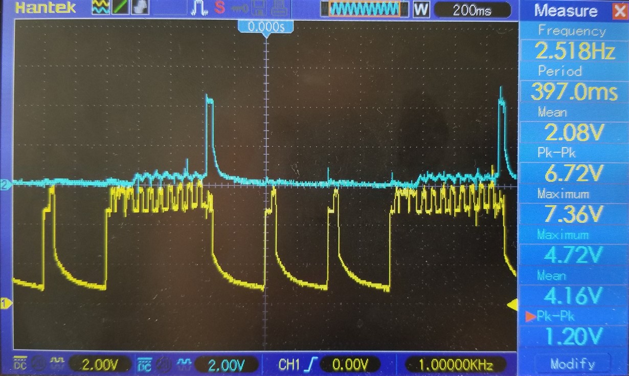
Pictured below is the result of placing the coil on the UNITX charger with no battery connected;CH1 is the RECT voltage and CH2 is the voltage on BATT. Some communication appears to succeed but the battery voltage fails to stabilize. charging light blinks whenever communication appears to succeed.
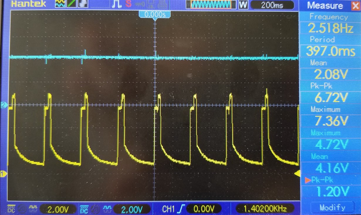
Connecting a battery in the system (and removing/replacingt the coil) shows the following behaviour; CH1 is the RECT voltage and CH2 is the voltage on BATT. Using a discharged battery yields very similar results.
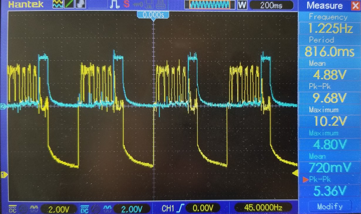
Using the Logiix fast charger does not seem to improve the issue as shown below, voltage is higher but behaviour is the same as with the other Tx.
Using a different coil 1461791001 we get different results, communication is attempted, fails and a fault is generated (Tx stops trying). Trying to match Cs and Cd does not seem to improve the communication either. Also attempted using the coil recommended in one of your designs http://katalog.we-online.de/pbs/datasheet/760308103206.pdf which somewhat improves the communication when no battery is present (it continuously communicate) but the battery voltage does not settle and when a battery is present the same behaviour is there; also once you put any distance between coils, it completely fails.
We've removed R12 and swapped R13 with a 10k with (again) no improvements. This procedure has been attempted in 4 different boards so at this point we are running out of debugging ideas and we are hoping to get some guidance as to what to attempt next. We did notice a capacitor is missing on FOD but again the addition of it on a board does not appear to have an effect on successfully charging the battery.
For batteries we have attempted using protected Li-ion batteries from EBL, Canwelum and Orbtronic as well as an un-protected Ultrafire battery.
Thanks in advance,
Juan Pablo Diaz


