Hi,
I'm designing a Buck-boost Automotive LED power supply with LM5175Q1, and below are the observations :
1. Buck mode is working properly up to 5A, even at lower currents as well.
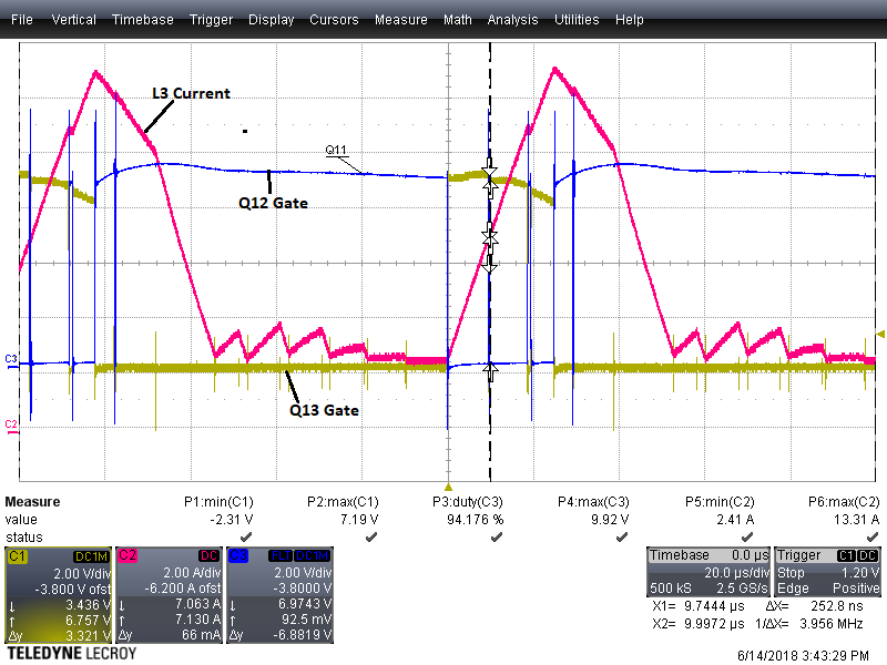
2. When Vin is lowered up to 9.5-10V, buck-boost transition mode kicks in, and then LDRV2 (boost leg low side FET) gets driven in a wider duty cycle, which overcharges the inductor up to 20-30A ! This causes huge acoustic noise, and damages Boost Leg FETs
I've used my own MathCAD calculation to determine the values and verified it against Buck-Boost Quick start tool as well (and they match !) . We have a 4 layer PCB, and tried to follow TI guidelines for layout wherever's possible,(Input cap, FET's and inductor placement is exactly as per TI reference layout) not to mention reviewed multiple times internally and with TI as well.
I tried a series of trials to rectify the issue, but every time I'm seeing that LDRV2 FET is getting driven by a wider pulse from the controller which is overcharging the coil ! We have secondary filter inductor at output, but tried without that as well, and till now nothing works ! Even current sense and voltage feedback signals look clean when it's operating in stable buck mode
Attached a small report . Looking forward to some urgent help from TI !
Regards,
Deb


