This thread has been locked.

If you have a related question, please click the "Ask a related question" button in the top right corner. The newly created question will be automatically linked to this question.

TPS65381-Q1: negative spike on SCLK and SDI

Part Number: TPS65381-Q1

Hi ,


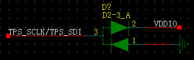
based on my customer's test, they use TPS65381-Q1 as power supply for TMS570 and they found there is negative spike on SCLK and SDI. Those SPI communication pins are connected directly between devices.

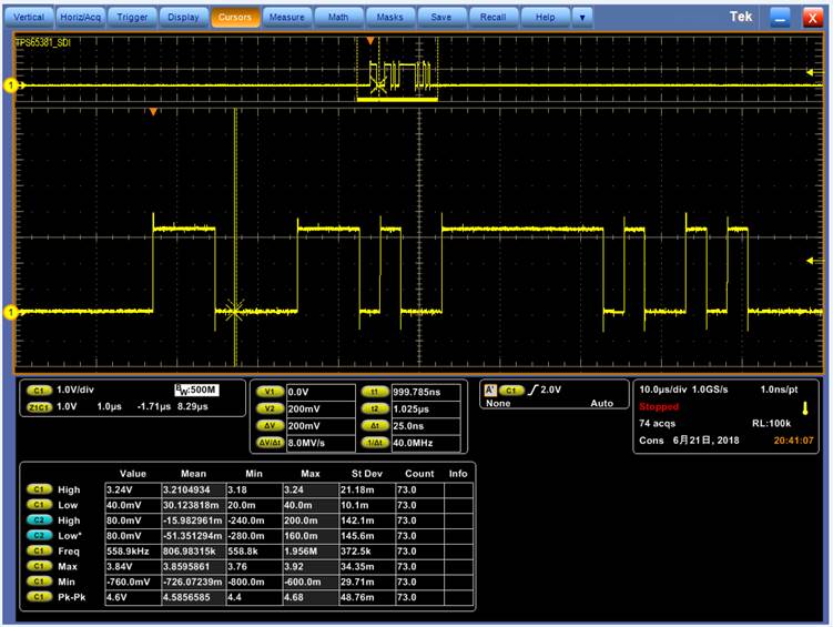
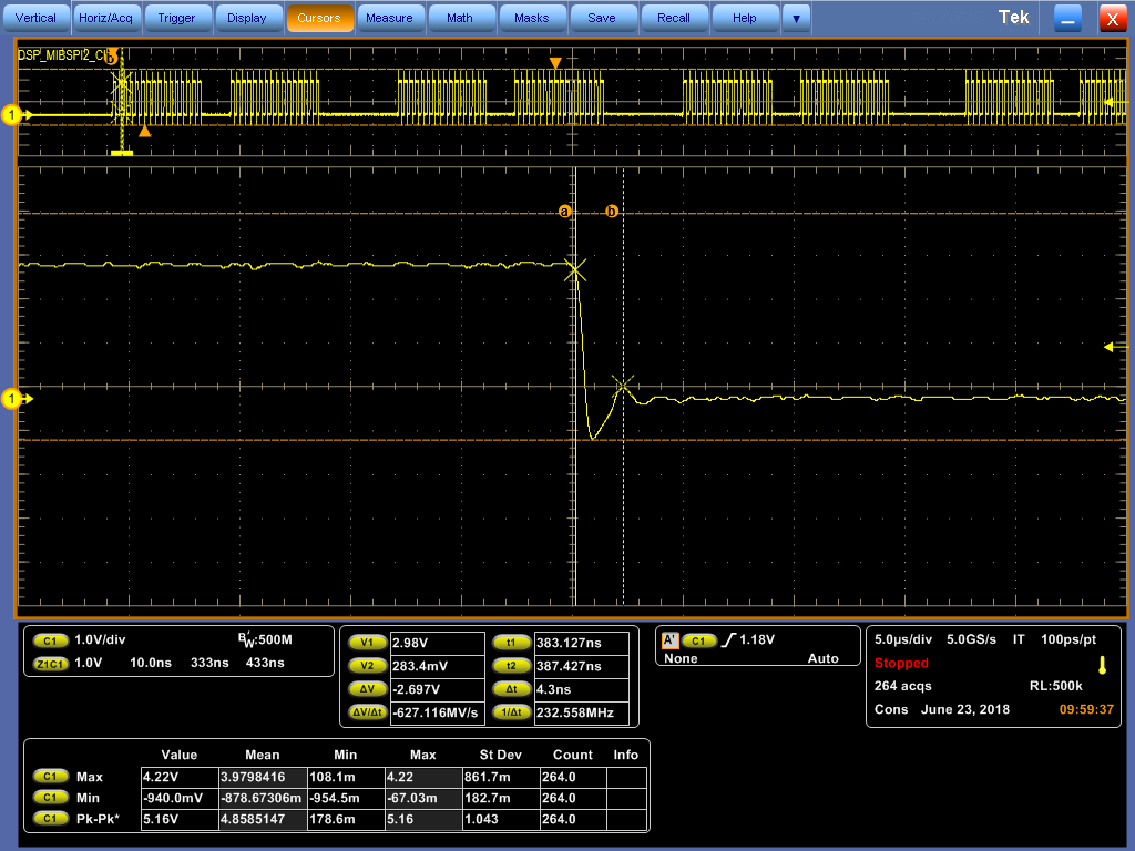
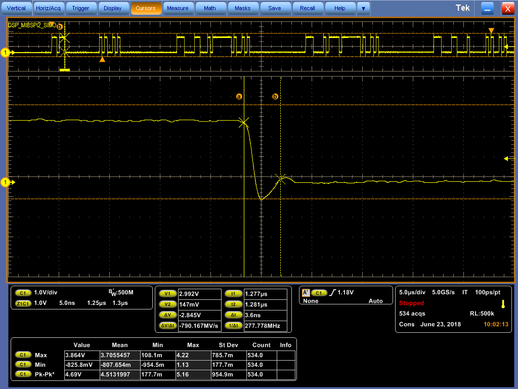
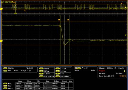
waveforms are as attached;

               SCLK: -0.8V ( <200ns)

               SDI   : -0.76V ( <200ns)

Please kindly help check if -0.8V( 200ns) will damage the part since spec says -0.3V and if there is AC spec on this.

Thank you.


BRs

Given


  • Hi Given,

    I've assigned this post to the appropriate applications engineer, he will respond to your question.

    Regards,
    Karl
  • Given,
    My first thoughts on this, is that there should not be over-shoot and under-shoot at these levels on the SPI lines. Usually this is caused by a poor layout with long data lines or by the test leads when they are connected, and will go away when the long test leads are removed.
    Regardless, The over-shoot is below the ABS MAX of 7V, so that is not a problem. The under-shoot threshold of -0.3V is the point where the ESD diodes start conducting. Because you are spiking to -0.8V the ESD diodes are conducting current during the 200ns that the spike is below -0.3V.

    In order to determine if this will damage the part, the customer will have to perform a temperature test on the IC. They will need to run the IC, with minimal load and no SPI until steady state has been reached to determine the nominal temperature rise of the package and die above ambient. Then Turn on the SPI data communications, and measure the package and die temperatures while the SPI is running. The time the customer must run the SPI test will be determined by the steady state temperature. When the package and die temperature has reached steady state, record the temperature rise above the previous nominal rise.
    If they see more than a 5 degrees C rise in the package or die above the nominal rise of the part, do to the SPI data under-shoot, then they may damage the part over time. If the temperature rise is much more than 10C rise then they are damaging the IC with the under-shoot.
  • Hi Gordon,

    Thanks for your reply. two more questions as below:

    1. what's the ESD diode architecture internally on SCLK and SDI? is it as attached? And for -0.8V, how much width of time will make ESD constructed? If ESD diode is constructed, negative voltage should be clamped to ~-0.3V, not -0.8V, right? Thanks.

    2. what's the reason and principle of your proposed solution to check if the negative voltage will damage the part?

    Also, have asked HW to use short lead to test and results are as attached. SCLK: -0.94V, 3.3ns, SDAI: -0.826V, 2ns.

    Looking forward to your reply today since it's a little urgent on my customer side. Thanks.

  • Given,
    The ESD structure you are showing appears to be correct.

    The -0.3V is approximately the point where the diode junction will conduct negative current. Just like a forward biased diode the voltage drop is dependent on the current and temperature. With a negative voltage on the diode, the diode will begin to conduct current at the threshold and that will change with current and temperature.

    You had asked if the negative voltage will damage the IC. The only way to know if the negative voltage will damage the IC is to determine the thermal effects on the diode. Measuring the temperature rise above normal operating temperature rise above ambient is the only way to determine if the negative spikes are damaging the IC.

    Remember, when you have a negative voltage spike the ESD diode will conduct. Each time it conducts current, there will be a small temperature rise. If this temperature rise becomes to hot then the diode will burn out. We are trying to determine if the negative spikes are pushing the ESD structure close to their limits.
  • Hi Gordon,

    Thanks for your reply.
    So short time like 3.3ns or 2ns will also make the diode constructed, right? And based on your reply that -0.8V may be caused by current and temperature, right? And temp of ESD structure is 5C rise? Thanks.

    BRs
    Given
  • Given,
    A chip designer has looked at the timing charts and thinks your problem is in the drive strength from the master. They want you to add 1k (or higher) resistors in series on the SDI and SCLK to protect the ESD structure and reduce the negative spike voltage to -0.3V or less.

    The undershoot is caused by strong drive current and Inductive traces on the PCB.

    Yes 2-3ns is enough to cause the ESD diodes to conduct.

    Yes the -0.8V is caused by the current and temperature. (-0.8V indicates strong drive current)

    The use of temperature measurements is valid and useful, however they feel like it will be a problem if you don't reduce the current in the negative spike.