This thread has been locked.

If you have a related question, please click the "Ask a related question" button in the top right corner. The newly created question will be automatically linked to this question.

LM5176EVM-HP: Switch node ringing on stock evaluation board

Part Number: LM5176EVM-HP
Other Parts Discussed in Thread: LM5176

Hello,

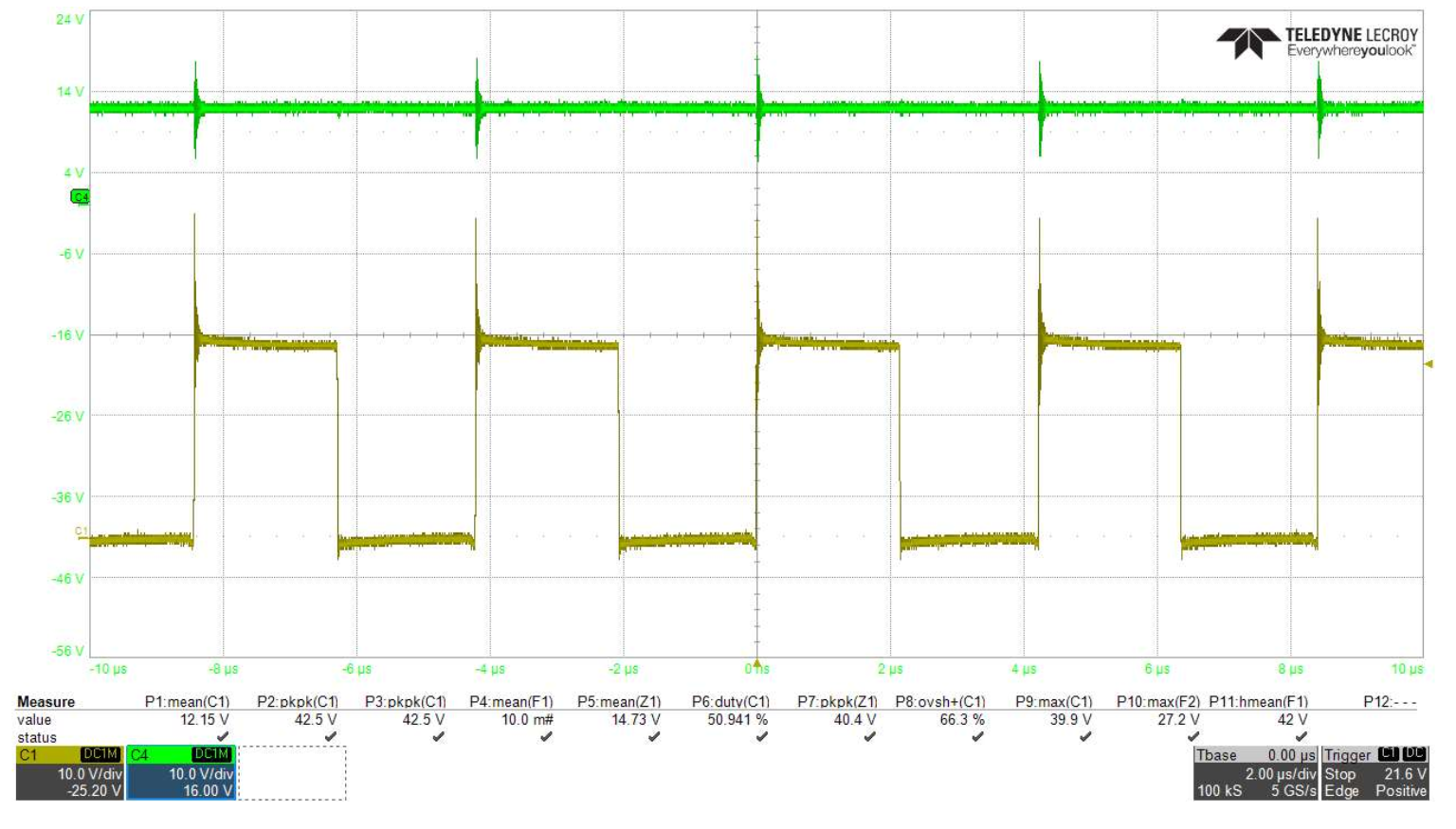
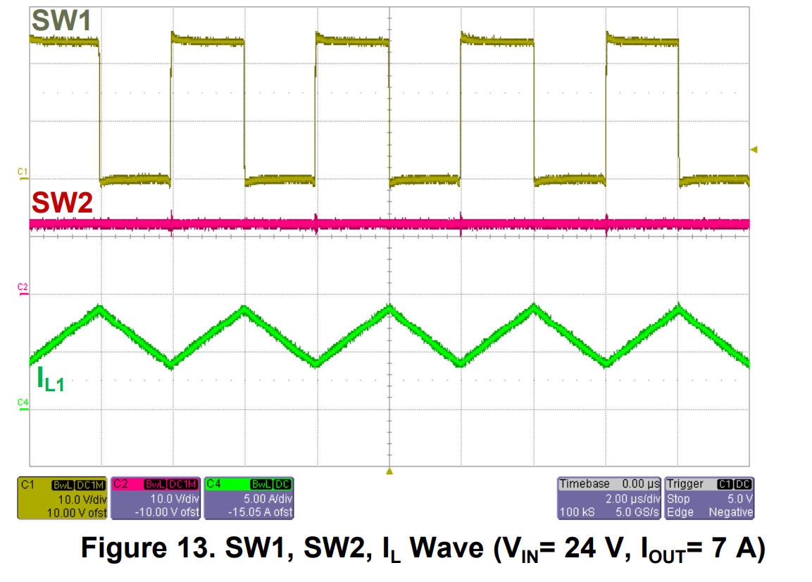
I just received the lm5176EVM board and am getting some very different results from the user guide for the board.  When connecting the device to our power supply and load I am seeing significant ringing and overshoot on the switch nodes at a nominally loaded condition (7A to match the graphs in the user guide).  Using the same sampling rate and time scale, the difference is very clearly visible on the attached graph( shows switch node 1 and output voltage). the second graph shows the graph from the user guide.  

A 24V input leads to spikes of close to 40V on the buck switch node and significant noise reflected on the output as well.  The voltage on the output spikes above 14V and is above the maximum spec for some of the devices we would like to power using the lm5176.  

If this reference design is exhibiting this behavior, it is hard to feel confident about using this component in any future designs.  

our capture:

 user guide image:

  • I am afraid this is the problem of measurement. If you use the regular scope probe, the long ground lead will pick up noise and the ringing or overshoot is not real. Please use the spring tip ground lead with the probe (come with most probe), which is a coil ground leads directly placed on the probe head (you need to remove the cap), and then apply the probe directly across the circuit node and GND to measure. You will get the cleaner waveforms as shown in the user guide.
  • Hi Youhao,

    Thank you for your prompt response to the question.  

    The original measurements were taken using the measuring method you suggested above measuring directly across the MOSFETs to ground.  Running evaluations on several other boards showed this to be necessary.  The setup is shown in the picture below. 

    The probe has been properly calibrated and compensated on the scope shows proper performance on a 5MHz square wave with a rise time faster than that on the eval board.  Probing the BNC output of the scope with the spring-lead tip and a 200 MHZ bandwidth limit on the probe shows no oscillation.  using the same setup on the eval board shows the same waveforms as my original post.  Bandwidth limiting the probes down to 20MHz shows a similar waveform to the user guide, but thi is masking noise that is present.  

    Increasing the load current increases the amplitude of the ringing which further points to board design as the cause.  Is there an eval board with footprints for an RC snubber circuit to reduce some of this noise?

  • Hi Andrew,

    There is not an orderable EVM with the footprints for the RC snubber. In the final PCB of your design these footprints can be added. This will allow for accurate tuning of the snubber.

    Thanks,

    Garrett