


Tool/software: Code Composer Studio
Hello.
1)
If I create an almost empty program.
#define MAIN (1)
#include "include.h"
Uint32 PRD = 0x3FFFF;
void DPWM0(void)
{
Dpwm0Regs.DPWMCTRL0.bit.PWM_EN = 0;
Dpwm0Regs.DPWMCTRL0.bit.CLA_EN = 0;
Dpwm0Regs.DPWMPRD.all = PRD;
Dpwm0Regs.DPWMEV1.all = 0;
Dpwm0Regs.DPWMEV2.all = PRD/2;
Dpwm0Regs.DPWMEV3.all = PRD/2;
Dpwm0Regs.DPWMEV4.all = PRD;
Dpwm0Regs.DPWMSAMPTRIG1.all = PRD/2;
Dpwm0Regs.DPWMCTRL2.bit.SAMPLE_TRIG_1_EN = 1;
Dpwm0Regs.DPWMCTRL0.bit.PWM_EN = 1;
}
void EADC(void)
{
}
void LoopMux(void)
{
LoopMuxRegs.CYCADJCTRL.bit.CYC_ADJ_EN = 1;
LoopMuxRegs.SAMPTRIGCTRL.bit.FE1_TRIG_DPWM0_EN = 1;
LoopMuxRegs.FECTRL1MUX.bit.DPWM0_FRAME_SYNC_EN = 1;
union GLBEN_REG glben_store;
glben_store.all = 0;
glben_store.bit.DPWM0_EN = 1;
glben_store.bit.DPWM1_EN = 1;
glben_store.bit.FE_CTRL1_EN = 1;
LoopMuxRegs.GLBEN = glben_store;
}
void main()
{
// ###################### WARNING!!!! LOOK AT THIS #######################
MiscAnalogRegs.IOMUX.all = 0;
// #######################################################################
EADC();
DPWM0();
LoopMux();
while(1)
{
}
}
void c_int00(void)
{
main();
}
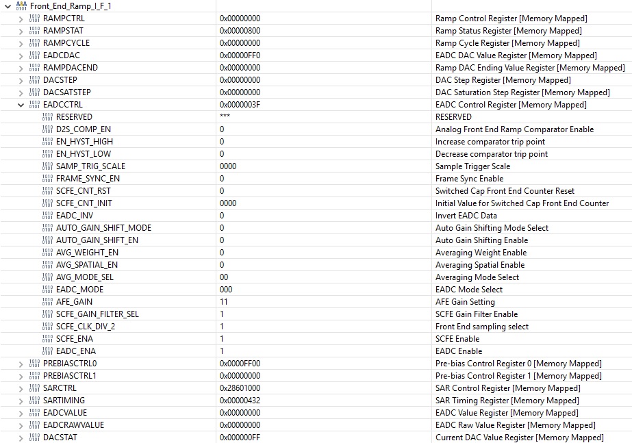
I'm in Debug mode changing the FE mode to a continuous SAR
The module works fine.
And I get the correct result.
This confirms that the module itself is in working order.
2)
But if I change the FE mode using the code:
...
void EADC(void)
{
FeCtrl1Regs.EADCCTRL.bit.EADC_MODE = 3;
}
...
That I receive such result:
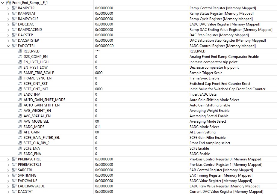
As you can see, the mode was set, but all the default settings were reset.
I spoke about this in a previous letter.
3)
If I set the standard settings myself using the program code:
void EADC(void)
{
FeCtrl1Regs.EADCCTRL.bit.EADC_MODE = 3;
FeCtrl1Regs.EADCCTRL.bit.AFE_GAIN = 3;
FeCtrl1Regs.EADCCTRL.bit.SCFE_GAIN_FILTER_SEL = 1;
FeCtrl1Regs.EADCCTRL.bit.SCFE_CLK_DIV_2 = 1;
FeCtrl1Regs.EADCCTRL.bit.SCFE_ENA = 1;
FeCtrl1Regs.SARTIMING.all = 0x432;
FeCtrl1Regs.PREBIASCTRL0.all = 0xFF00;
FeCtrl1Regs.SARCTRL.all = 0x28601000;
FeCtrl1Regs.EADCCTRL.bit.EADC_ENA = 1;
}
then I get the same settings as the default ones.
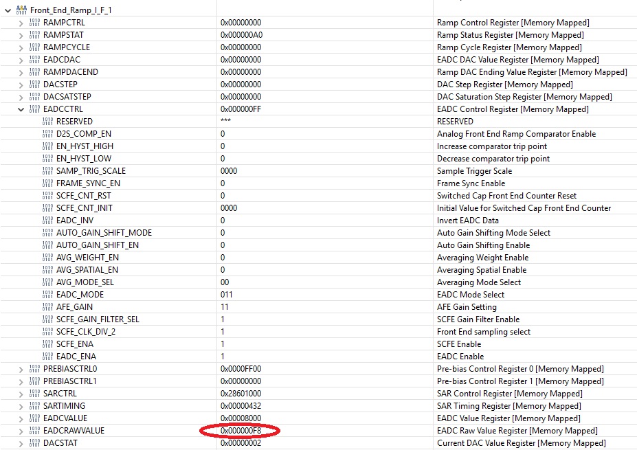
But the module does not work correctly, EADCRAWVALUE = 0хF8 and does not change.
This is normal if the DAC has a low value.
But the DAC automatically changes the value in SAR mode.
1000000000b
0100000000b
0010000000b
...
0000000001b
The voltage at the input of EAP1 is the same as in the first case.
Thank you for your help.

