This thread has been locked.

If you have a related question, please click the "Ask a related question" button in the top right corner. The newly created question will be automatically linked to this question.

LMR36015: Review request for Altium Layout

Part Number: LMR36015

Hey all,

I am currently working on a PCB in Altium. I'm utilizing the LMR36015 as my step-down converter. Would anyone familiar with Altium be able to review my layout and provide some feedback?

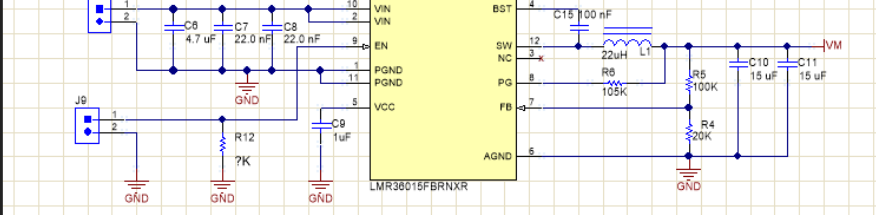
Below you see the diagram of the LMR36015 with its external network:

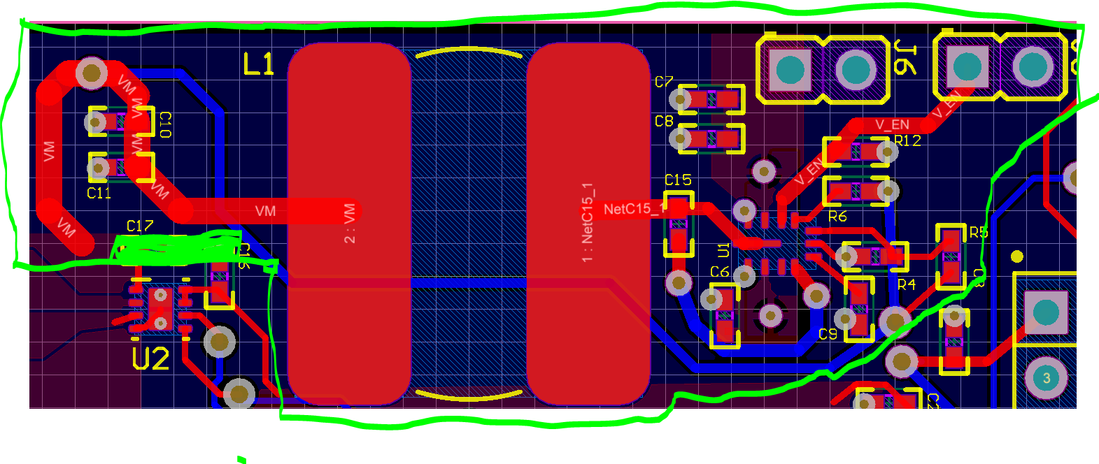
This is my representation of it in Altium (Everything within the green lines):

Any help is appreciated. Thank you!

  • Hello Blake,

    I would recommend using the EVM layout as a starting point: www.ti.com/.../lmr36015aevm I have also received your e-mail request for the review, and I can share the EVM Altium files with you via e-mail. You can also look at Page 25 on the datasheet for layout guidelines:www.ti.com/.../lmr36015.pdf

    My recommendations for your schematic are as follows:

    1. What are the input and output conditions of this design? It will determine the recommended output inductor and capacitance.
    2. In the datasheet, it is recommended to tie NC to SW. This will make the layout easier for the boot capacitor. You can look at the EVM layout for an example of how to place the boot cap as close as possible to the device.
    3. Tie Enable high to enable the device. You can tie this pin to VIN through a pullup resistor.

    For the layout, my initial recommendations are:
    1. Place C7 and C8 as close as possible to the device. They should be placed symmetrically on either side of the device.
    2. What is the voltage rating of C6?
    3. There should be a ground plane coming from Pin 6. Please look at the EVM layout for an example.
    4. The VCC cap (c9) should be rotated 180 Degrees, so that the device sees the AGND pin directly.
    5. Please rotate R6 90 degrees in the opposite direction, so both the FB and AGND pins are as close to R4 as possible.
    6. R6 and R7 should be have two separate traces to VOUT
    7. Is this a 2 layer board? A 4 layer board will provide additional layers for ground planes allowing you to spread the heat from the switch mode power supply.

    Best Regards,
    Katelyn Wiggenhorn