Because of the Thanksgiving holiday in the U.S., TI E2E™ design support forum responses may be delayed from November 25 through December 2. Thank you for your patience.

This thread has been locked.

If you have a related question, please click the "Ask a related question" button in the top right corner. The newly created question will be automatically linked to this question.

LP8860-Q1: EMI issue

Part Number: LP8860-Q1

Hi,

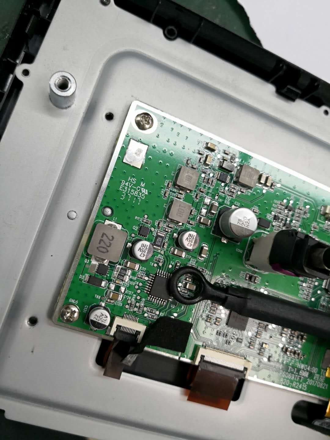
My customer uses LP8860-Q1 in one of their display modules, they failed the EMI conduction test in 80M/90M/100MHz.

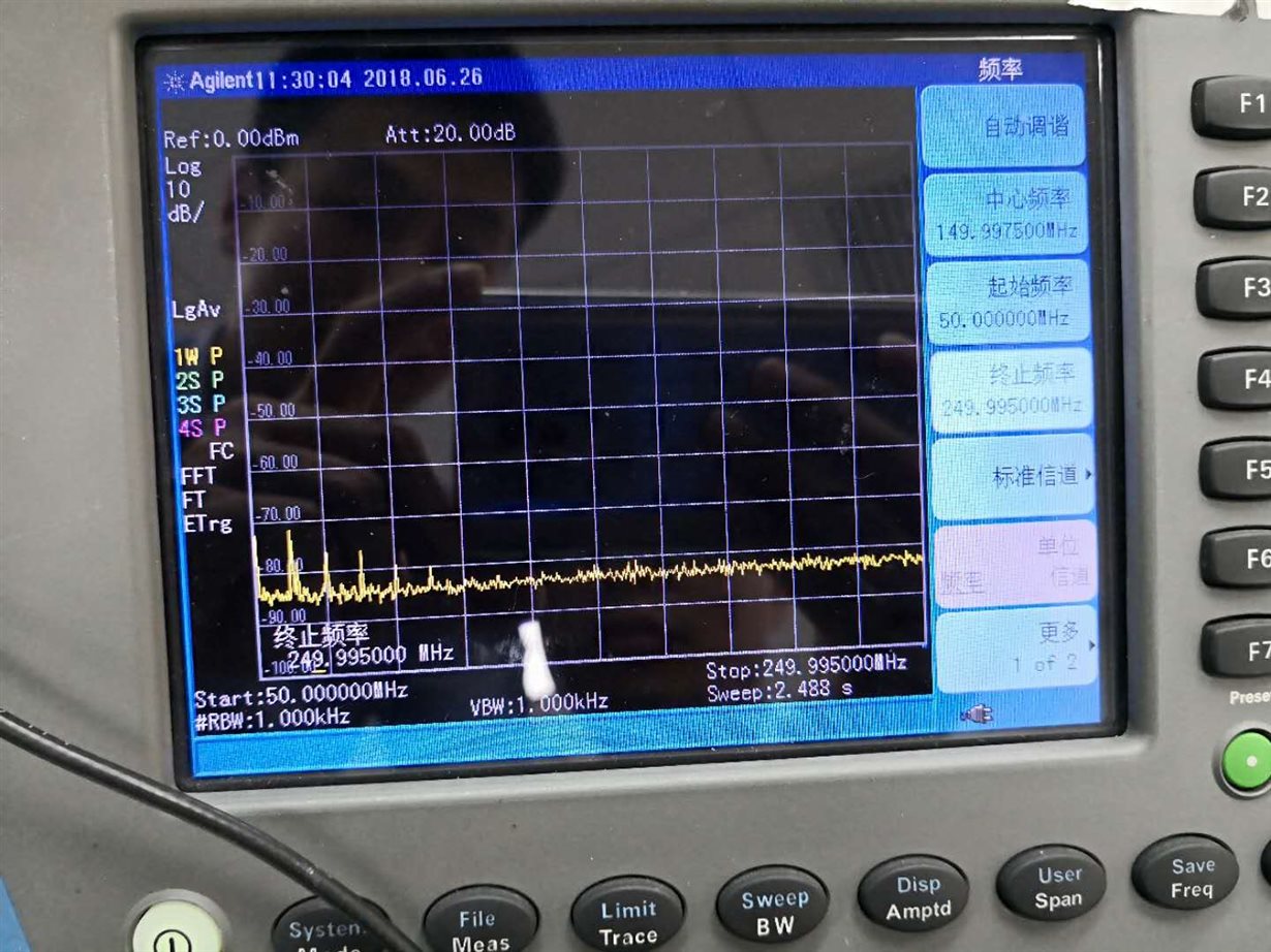
I am thinking if there is something to do with LP8860 since it has a 10MHz internal clock which matches well the failed frequency. We use near-field frequency spectrum to test the LP8860, we do find the 10MHz peak frequency and its harmonics.

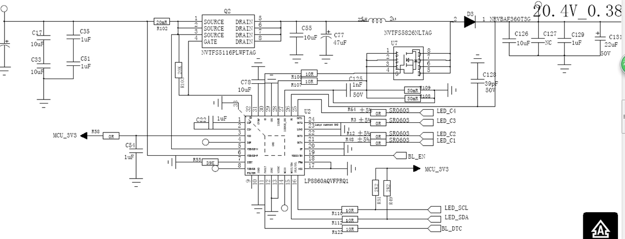
  • I attach the schematic and eeprom, according to customer's setting, EN_PLL=1 and FILTER pin is floated, is that the root cause? Can we use internal 5MHz osc directly and disable PLL?
  • Could you also double check the schematic and eeprom, what are the possible reason for 10MHz peak frequency?
  • For the boost input and output capacitor, is that ok to use below value? what are the risks?

EEPROM reading:

(T8U)0x60,(T8U)0xEA,
(T8U)0x61,(T8U)0x21,
(T8U)0x62,(T8U)0xDC,
(T8U)0x63,(T8U)0xF0,
(T8U)0x64,(T8U)0xC7,
(T8U)0x65,(T8U)0xF5,
(T8U)0x66,(T8U)0xF2,
(T8U)0x67,(T8U)0x77,
(T8U)0x68,(T8U)0x77,
(T8U)0x69,(T8U)0x71,
(T8U)0x6a,(T8U)0x37,
(T8U)0x6b,(T8U)0xB7,
(T8U)0x6C,(T8U)0x17,
(T8U)0x6D,(T8U)0xFF,
(T8U)0x6E,(T8U)0xB9,
(T8U)0x6F,(T8U)0x87,
(T8U)0x70,(T8U)0xC9,
(T8U)0x71,(T8U)0x72,
(T8U)0x72,(T8U)0xE5,
(T8U)0x73,(T8U)0xDF,
(T8U)0x74,(T8U)0x35,
(T8U)0x75,(T8U)0x06,
(T8U)0x76,(T8U)0xDE,
(T8U)0x77,(T8U)0xFF,
(T8U)0x78,(T8U)0x3E

Best regards.

Dongbao

  • This thread has been assigned; Someone will reply shortly.
  • Hello Dongbao,

    Thank you for promoting LP8860-Q1 and reaching out.

    There could be some limitations about how much you could improve EMI but the following (below) are some considerations that have been successfully implemented in the past and helped to reduce EMI levels to acceptable levels:

    1. Gate resistor, BOOST_DRIVER_SIZE[1:0], and FET selection. These are the three first things I would consider:

    (i) From the schematic it seems that you are using the 10ohm gate resistor (for boost FET). That value is the general recommendation but some customers have successfully been able to use slightly higher values without penalty on the performance (as it would be expected if you went to the other extreme and increased it too high). If a slightly higher FET resistor is acceptable (not high losses) that could help improve EMI performance. This level of evaluation is usually done by the customer and it could greatly help.
    Has your customer explored this option?

    (ii) Another options that could be used (isolated or in conjunction with the above consideration) is to select the min Max gate current sink/source by selecting the lowest possible value of BOOST_DRIVER_SIZE=00 register. This has also been successfully implemented in the past by some customers and helped them meet EMI requirements justifying some sacrifice on the efficiency.
    Has your customer explored this option?
    Decision should be based on gate charge (of the NFET) considerations (based on bench measurements).
    From your EEPROM settings it seems that you are using the highest BOOST_DRIVER_SIZE settings.

    (iii) Potentially selecting a FET with relatively higher gate capacitance and package with better inductance could help as well. I understand there will be limitations with this.

     Find a summary below about these three points (the first two ones are important).

    2. PCB layout:
    In addition to the above of course PCB layout could play a role. Although assuming the customer has followed a good PCB layout practice and/or EMI requirements are too stringent the return value of re-optimizing the PCB may need to be re-evaluated since a fairly decent PCB layout often doesn’t render the expected EMI performance by just re- tweaking it. Has the PCB layout been reviewed to ensure good loop and EMI considerations?

    3. EMI mitigation/reduction circuitry:
    What other additional circuitry has been considered to improve EMI?
    Please refer to the following link for more details
    www.ti.com/.../snva813.pdf

    >>>
    SUMMARY OF POINT 1 ABOVE:
    1. Ringing on the gate voltage could be improved by:
    (a) Increasing value of gate resistor (some customers have successfully tried higher than 10mohm without sacrificing performance and getting a good EMI improvement in return).
    (b) Selecting the minimum Max gate current sink/source (0.4/0.45A) defined by BOOST_DRIVER_SIZE=00
    (c) Selecting a FET with relatively higher gate capacitance and package with better parasitic (L).
    >>>

    Now, in terms of passive selection (CIN and COUT): the right choice would obviously depend on your settings, conditions, and requirements. The datasheet provides some general recommendations and there could be some flexibility depending mainly upon your specific conditions/requirements. For example depending on the quality of your input signal you could relax a little bit CIN. The optimum value of COUTwould depend on acceptable VOUT ripple values and stability considerations. Often it is more challenging to be able to relax COUT than CIN but, ultimately stability measurements and ripple measurements using your conditions would determine whether you could safely deviate COUT from the datasheet general recommendations.

    I hope that helped.

    Kind Regards,

    David
  • Hi David,

    Thanks for your quick reply.

    Could you also give some comments on my question 1 regarding clock generation?

    I am thinking whether float FILTER with EN_PLL=1 affect the EMI performance, because the 10MHz frequency may come from the VCO.

    1.  I attach the schematic and eeprom, according to customer's setting, EN_PLL=1 and FILTER pin is floated, is that the root cause? Can we use internal 5MHz osc directly and disable PLL?

    Best regards,

    Dongbao

  • Hi David,

    Could you help give some comments on my question? Thanks.

    Dongbao

  • Hi Dongbao,

    I agree that the 10MHz clock could give you some trouble and it may be worthy to try some other options and see how EMI performance behaves (for example as you suggested if you could afford disabling PLL / using different osc freq).

    Also, I would seriously consider the options we discussed in my previous email.

    Kind Regards,
    David