Hi Team,
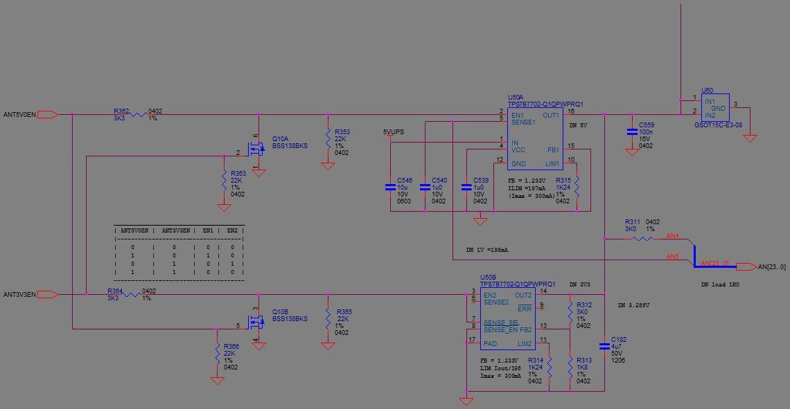
Do you have any comments on circuit below, is the design ok?
U50B output should be 3.3V (ANT3V3EN = H, ANT5V0EN = L), actual output = 0V
U50A output should be 5V (ANT5V0EN = H, ANT3V3EN = L), actual output = 5V
From the data sheet SENSE2 pin (6) should connected to GND, is this correct for the configuration below.
SENSE1 — 5 O Output of current sense for sensing. SENSE1 current is proportional to the current flow through
OUT1 and SENSE 2 current is proportional to OUT2 current when SENSE_SEL and SENSE_EN
are low. To set the SENSEx output voltage level, connect a resistor between this pin and GND. In
SENSE2 — 6 O addition, connect a 1-μF capacitor from the SENSEx pin to GND for frequency compensation of
the current-sense loop. Short the SENSEx pin to GND if not used.
The ERR pin (9), is always asserted, the data sheet states this open drain output is internally pulled up.
Any help would be greatly appreciated.
Regards,
Ross


