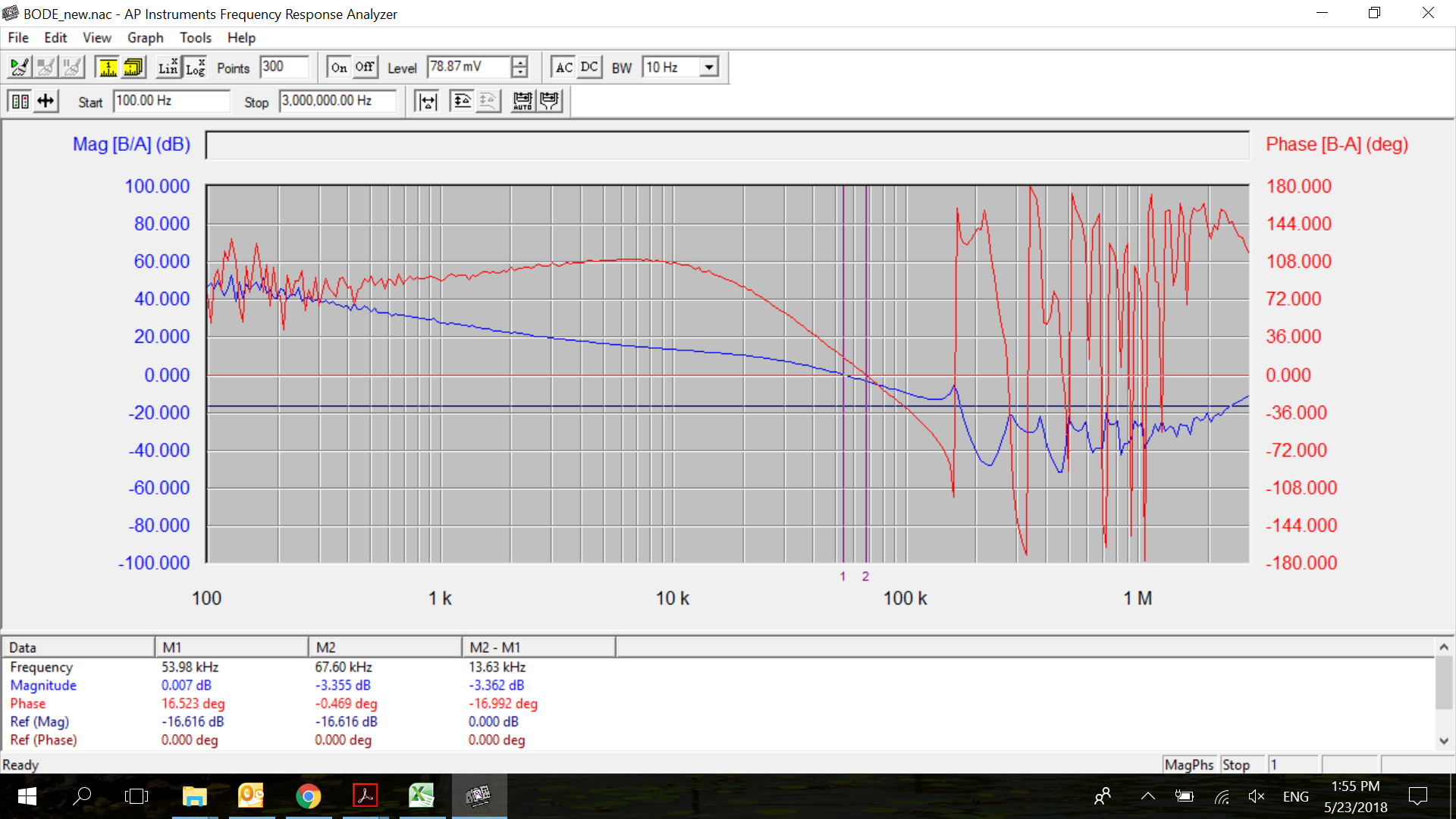
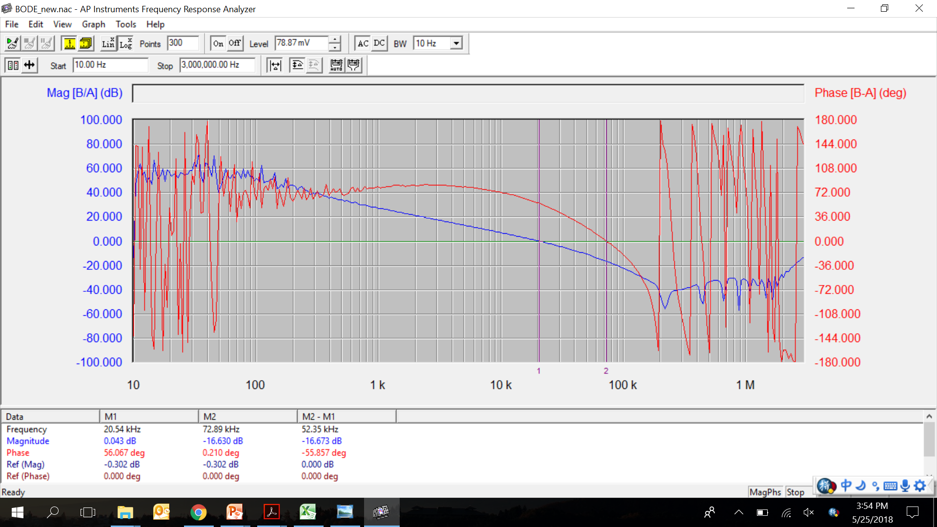
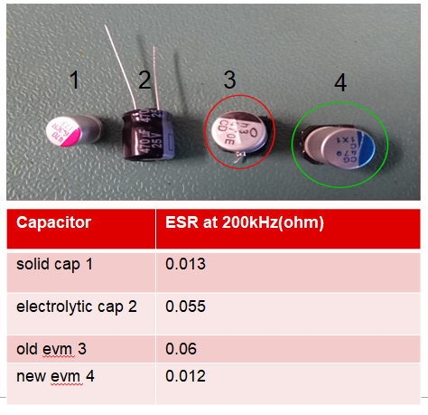
Hi team, I tested a LM5117 EVM without any modification, the bode plot is as blow with Gain Margin:5.32dB and Phase Margin:27.10deg, does not meet the loop requirement. Then I tested a new LM5117 EVM, the bode plot is as below with Gain Margin:17.87dB and Phase Margin:59.93deg. I checked with this two EVM boards, the only difference is the 470uF output capacitor, comparation as below. For the 470uF output capacitor on LM5117 EVM, on the BOM is NICHICON, PCG1C471MCL1GS, the datasheet shows it is a solid cap. But in the old evm I tested the capacitor has indentation for explosion protection which is common seen on electrolytic cap. On the new EVM the capacitor is solid cap without indentation for explosion protection.
I am not sure if there is same specification capacitor on the EVM board?
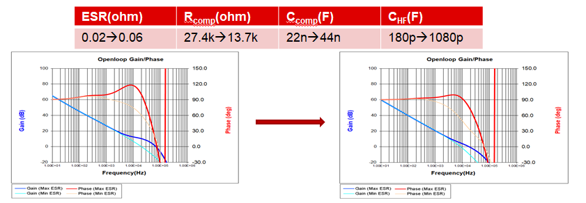
I test the ESR of electrolytic cap and solid cap, I used the Calculator and WEBENCH to adjust higher ESR to study the effect to verify my assumption that the higher ESR of output capacitor brings the compensation of LM5117 EVM does not fit for the requirements. Need to reduce the Rcomp to reduce the cross-over frequency to compensate the changed zeros. Then the Gain margin rises from 8.9dB to 17dB, and Phase margin rises from 37deg to 58.4deg, to meet the requirements.