This thread has been locked.

If you have a related question, please click the "Ask a related question" button in the top right corner. The newly created question will be automatically linked to this question.

TLC59401: Extrange behavior of TLC59401

Part Number: TLC59401
Other Parts Discussed in Thread: TLC5940

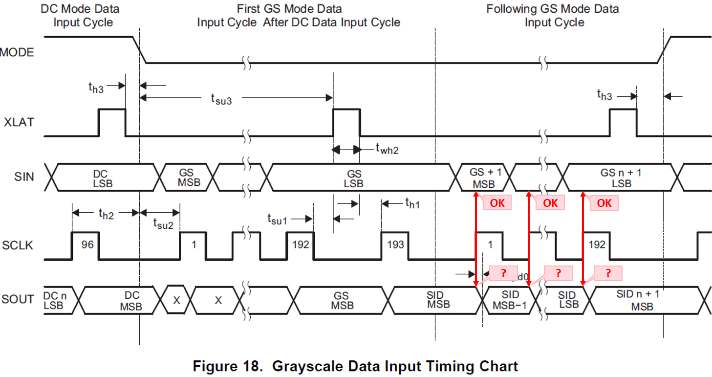
I'm trying to use two TLC59401 in series but none of them work. I have tested all signals (MODE, XLAT, SIN, SCLK, BLANK, GSCLK) in a logic analyzer and all seem correct, except for SOUT, which is not in sync with the clock. The following screenshoot corresponds to bits 193 to 204 (the first 12bit value that should be sent to the second TLC59401). The value should be a "2". As you can see it is correct in SIN but it is shifted left in SOUT. Could the chip be wrong? (I have tested two chips and both have the same behaviour) 

None of the chips work. I'm not able to light any LED.

Extrangely enough, the only way LED are ON is if I insert the GSCLK signal in the BLANK input.  Then I can controll the LED current (DC) but not the PWM (GS) ¿!?

Best Regards

Hector

  • Hi, Hector,

    Do you try just using one TLC59401?

    Does it work normally?

    Thanks.
    Regards,
    Kenneth
  • Ye I have tried with one chip and it doesn't work either.
  • I can see that the specification doc  is consistent with my data from SOUT. The value of SOUT at the rising edge of SCLK is undefined, how can the second chip work at all? Is Figure 18 of the specs correct? 

  • Hi, Hector,

    SID is the Status Information Data, and you can refer to the STATUS INFORMATION OUTPUT section. It's used to read LOD/TEF information.

    Here I also attach the code for TLC5940 for your reference:

    TLC5940 Sample Code.zip

    It drives 3 devices.

    Please let me know if this solves your problem.

    Thanks.

    Regards,

    Kenneth

  • Thanks very much Kenneth!

    I'm testing with just one chip and still I'm not able to make it work. I have tested already with 6 different chips just in case there was a problem with the chip, but all of them behave similarly.

    I have studied the sample code you send and it is the basically the same as my code. It all seems correct. I do not think I have a problem with the implementation of the serial data interface because of the following test:

    • If I put a clock signal in the BLANK input the LEDs do swith ON  ¿!!?
      • If I set the GS and DC values =0 then the LEDs do not swith on
      • If I set values different fron cero, the intensity is more or less proportional to the value of DC so the chip must be reading this value
      • The Intensity is not proportional to the value of GS, but the LEDs with a GS value of cero do not light ON, and the LEDs with a GS value of 4095 have more intensity than the ones with a GS value of 1 so the chip must also be reading the GS value

    Any idea of what could be happening?

    Regards

    Hector

  • Concerning what you mention about the Status Information Data, it is not only the SID signal which changes its value at the rising edge of SCLK, it also happens with GS as you can see in Fig 18 Greyscale Data Input Timing Chart.   I would think it is an error in the figure if it weren't because it is consistent with what I see in my signal analyzer. I can't understand how a second, third.. chip can work at all

    Regards

    hector