This thread has been locked.

If you have a related question, please click the "Ask a related question" button in the top right corner. The newly created question will be automatically linked to this question.

TPS2595: Strange behaviour of fault output.

Part Number: TPS2595
Other Parts Discussed in Thread: TPS2061C, TPS2041C

I have deisned a four port USB hub, using the TUSB2046. For downstream power switches. I used the TPS259533, which has active low enable and active low fault indication. The hub is primarily for use as part of an in-house testing system.

The power for one of the downstream ports can be controlled by an external logic signal, which overrides the #EN signal coming from the TUSB2046. This port is typically connected to the unit under test (UUT). When I operate this disable signal, the ouput is latched off, and the #FLT output stays low. This condition can only be cleared by cycling the power, or resetting the TUSB2046. This is not what I expected. I would not expect turning the output off to result in a fault being asserted.

When I tested the short circuit fault behaviour of the TPS259533, I found that the current limit worked correctly, but no fault was asserted. This is even more worrying.

I thought that perhaps my supplier (Farnell) had shipped incorrect parts, as there are 12 variants of TPS2595. However, the chip marking (ES33) was correct.

Looking at the variants of TPS2595, there is no variant that behaves as above. The #FLT output is behaving as if it is a Quick Output Discharge (QOD), which would go low when the output is disable, and not go low on a fault. However, the only variants that have QOD instead of 8FLT are TPS259525 and TPS259535, and these would not work, as the enable is active high.

I replaced the TPS259533 chips with the TPS259573, which should work fine for me. However, the behaviour was the same.

Am I misunderstanding these devices, or maybe the  TUSB2046?

  • Hi Adgie,

    Thanks for reaching us on E2E. The variants TPS259533 and TPS259573 should not latch off. Can you help with waveforms of Vin, Vout, EN voltage and input current in 100ms/div time scale for both the devices.

    Best Regards,
    Rakesh
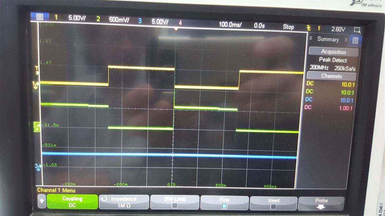
  • Trace1 = \EN, Trace2 = Vout, Trace3 = \FLT. Measuring input current will require modifying the board to add a sense resistor between the on-board 5V regulator and the input to the chip. This test was on the TPS259573.

    I have a second board partly built, which has the original TPS259533 power switches. I will do the same test when that board is completed.

    I want to send you a circuit diagram, but my PDF does not display properly in my post. How do I insert a PDF?

  • The board using the TPS259533 shows identical \EN and \FLT behaviour to the TPS259573 result shown above.

    In the absence of a circuit diagram, here are the details of the main components connected to the power switch.

    1 SS 10nF to GND
    2 \EN 15k series to \PWRON output on TUSB2046
    3 IN +5V 100nF to GND
    4 IN connected to 3
    5 OUT 100uF to GND
    6 \FLT 15k pullup to 3V3. Connect to \OVRCUR input on TUSB2046
    7 ILM 3k9 to ground. Approx 0.55A current limit.
    8 GND

    Function generator connected directly to \EN.
    100R load on output.
  • Overcurrent test. An N-channel MOSFET was used to switch a 1 ohm load resistor across the output. The MOSFET gate was driven from the function generator.

    Trace1 = Vout. Trace2  = Iout (voltage across 1R0). Trace3 = \FLT (steady 3.3 V).

    Current limit is a little over 0.5A, as expected.

  • I think I know why \FLT is asserted when \EN is high on the TPS259573. The \EN pin is actually an OVLO input on this device, so turning off the output by taking \EN high flags an OVLO fault. The TPS259533 also does the same thing, which I did not expect.

    I still do not know why an output overload does not flag a fault.

    For my USB hub, I think it would be better to use a power switch more suited to typical USB applications, such as TPS2041C or TPS2061C.

    I would still like to use TPS259533 in another application, which is to control Vbus for a GSM dongle, which takes a rather large Vbus current (3A peak). The behaviour of the \FLT output is not critical in this application, but it would be nice to know how \FLT should behave on output overload.

    If you can clarify how \FLT should behave, I can mark this issue as resolved.
  • Hi Adgie,

    Thanks for the test waveforms and your interest in this device.
    During overload, the device does current limit by dropping excess voltage across the device. This leads to junction temperature rise and eventually device thermal shutdown. The time to take it to thermal shutdown depends on the amount of overload, PCB, ambient conditions and it follows "Figure 59. Thermal Shutdown Limit Plot" in the datasheet. Only then \FLT will get asserted.
    For your case, Vin =5V, Rl=1ohm, Ilim=0.5A --> vout = 0.5V
    so the power loss across the device = (5V-0.5V)*0.5A=2.25W. As per Figure 59, at ambient temperature, it will not lead to thermal shutdown and will not assert \FLT. Hope this answers your question.

    Best Regards,
    Rakesh
  • Thanks, Rakesh.

    Your explanation of the behaviour of \FLT on overload clears up my remaining problem with understanding the device. The TPS2595 series are useful as current-limited power switches in general cases, but for interfacing to a USB hub controller in particular, other devices are more suitable.