This thread has been locked.

If you have a related question, please click the "Ask a related question" button in the top right corner. The newly created question will be automatically linked to this question.

TPS65721: TPS65721 charger doesn't work

Part Number: TPS65721

Hello, 

Were are using the TPS65721 for the first time in our project and we need to charge a LIPO battery with it. For now, we are not interested by the DC/DC, LDO or GPIOs functions. 

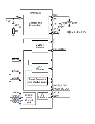
We have developed a small PCB to test the charger and we have set the TPS65721 like this : 


So we are just want to test the charger bloc :

- 5V on AC input

- LIPO battery on BAT pin

- 1K on ISET 

- 10K on TS

The chip start and we can communicate with it via I2C, read and write into registers. But the charger won't start when we put a Lipo on BAT pins.

When have checked the 1 register and saw that the charger is enable and the power source is good.

The temperature is also good, so the charger is not in temperature protection mode.

But charger won't charge the battery.

If someone have an idea about what's going on... Thanks :)

  • Hi Douki,

    The device experts on this part are out of office until next week due to US holiday, please allow for some delay.

    In the meantime, would you be able to provide a register dump of the state of the TPS65721 when the charger is enabled but no output is seen? That may help to identify the state the device is in.
  • If possible, please provide a copy of your schematic showing the TPS65721 connections.

    And we will need a Register Dump to review the state of the TPS65721 and look for any possible issues with the digital configuration.
    Simply read all of the Registers of the PMIC via I2C and send them as a text file or copy them in your reply.
  • It appears to me that you are creating an issue with the order of events in your test:

    1) Apply AC = 5V
    2) Test I2C
    3) put a LiPo on the BAT pins (insert battery)
    4) test for battery charging

    There is a paragraph in Section 8.3.10.6.1 of the datasheet that says: "This function is available as long as there is a voltage at the battery. After the battery was removed or was discharged, first power-on needs to be done by pulling PB_IN = LOW."

    Although this section is describing the Enable pins for DCDC1 and LDO1, it is also suggesting how the state machine of the device will operate.

    When you perform your test again, measure the voltages at the SYS and BAT pins when you apply power at AC.

    And try changing the order of events such that the battery is installed before you apply power at AC:

    1) put a LiPo on the BAT pins (insert battery)
    1) Apply AC = 5V
    3) Test I2C
    4) test for battery charging

    And if you ever notice the the SYS voltage is not equal to VAC or VBAT (the greater of the 2 when both available), try pressing the Push Button connected to PB_IN pin. After you press the Push Button (PB_IN toggles low, then returns high), the SYS pin voltage should be high.
  • Hello Brian, 

    Thank you for your quick response. Indeed, the order of events is very important and it is one issue that we solved. Sometime we putted 5 V first and didn't use the PB_IN to activate DC/DC and LDO.

    But we find the main issue, the TS pin resistor. There was a mistake with the value of this resistor so the system was locked on temperature protection mode.

    After we change the value and put a 10K, everything worked fine.

    Thank you again for your support.

    Best regards, 

    Idir