This thread has been locked.

If you have a related question, please click the "Ask a related question" button in the top right corner. The newly created question will be automatically linked to this question.

TPS4H160-Q1: Error of open load detection report

Part Number: TPS4H160-Q1

Hi All,

Customer is using TPS4H160, and find a unexpected error of the driver IC, set up as follow:


1)IN1=0,Diag_EN=5V, LED load is well connected.

2)when VBAT=6.4V,8.4V, nFault=0V, means fault;

3)when VBAT=12V, nFault=5V ,means no fault;

4)Test waveforms are added in the appendix file.

Circuit as below

Vbat from 8.9V to 12V

Vbat from 10V to 8.9V

Please help to analyze the reason, thanks.

Best Regards

Charles Zhang

  • Hello Charles,

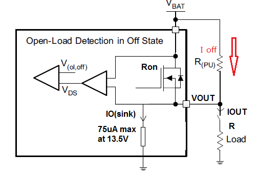
    Is that possible to send the schematic or partial schematic showing the output pull up resistor and the load (LED)? I belive the issue is due to LED bias with the pull up resistor. The LED is different from load resistor. If the current is very low in the LED it acts as open load (lower supply voltage) but small current can bias the LED (higher supply voltage? What is the VDS voltage in both cases? I could not see it well in the scope pictures but I will double check.

    Regards 

  • Rpull up=20k;

    LED is the normal SMD pakage, with power rating of 1W, and the LED is always lighted by the leakage current, so the equivalent of LED is very low;

    VDS means the inner switch MOSFET's DS voltage;

  • Hello,

    I believe what happens is at higher supply voltage, the LED leakage current is higher. This leads to lower impedance between VOUT and ground. The volltage drop Vds across the FET is higher. In this case the diagnostic can not recognize an open load and the FAULT goes high.

    Regards,