This thread has been locked.

If you have a related question, please click the "Ask a related question" button in the top right corner. The newly created question will be automatically linked to this question.

UCC2818: How to improve the THD of UCC2818

Part Number: UCC2818

Dear!

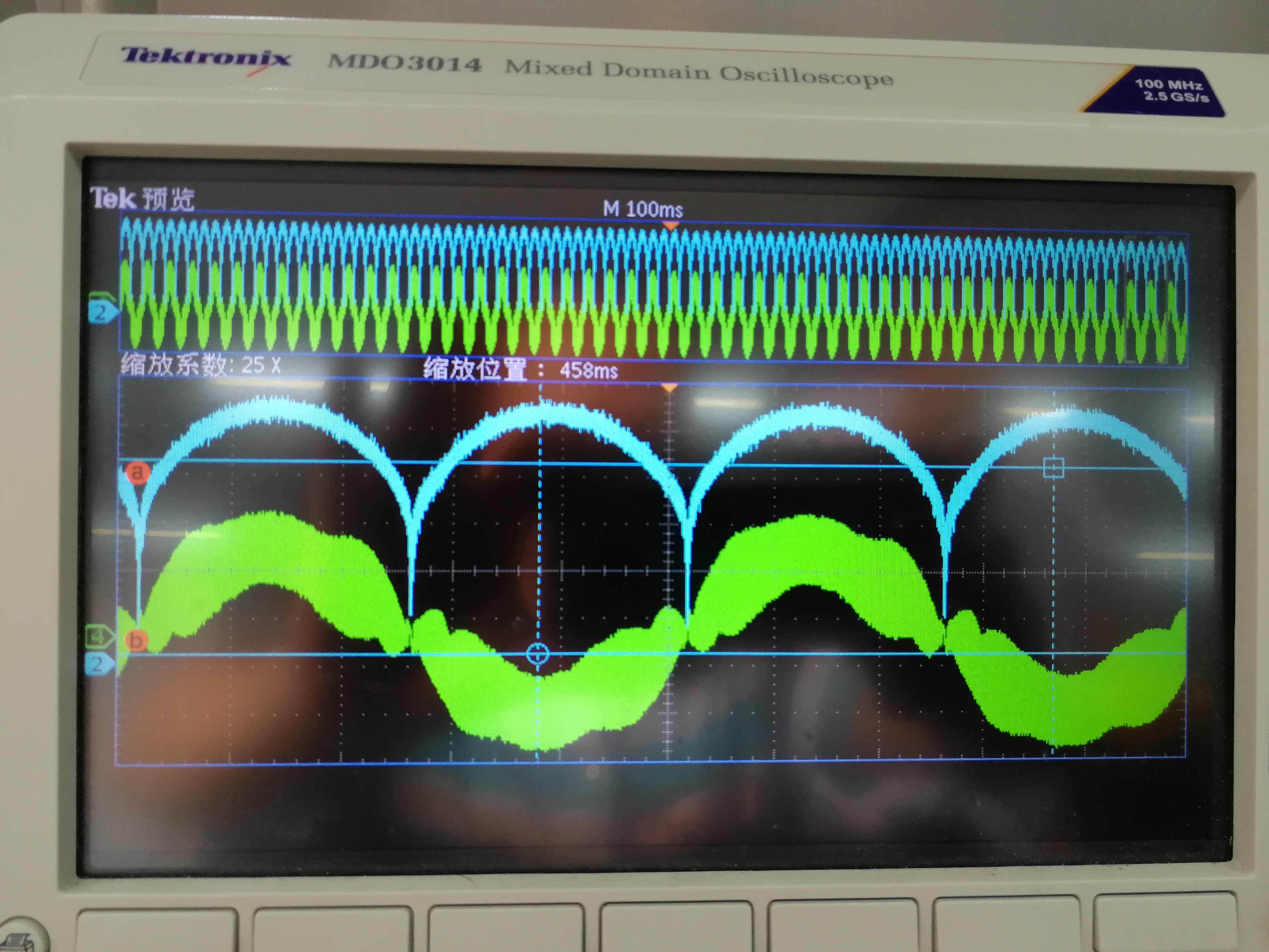
         I have a proble when i use UCC2818 as pfc control device,The wave profile is well,but the THD of current is bad, which is above 12%,Can you provide some method to improve the THD? 

normally how well can do of the THD using ucc2818?

                                                                                                                                                                                                                                                                                 Thanks


  • Hi,

    Can you please quantify your results with some data?
    You will needs some of the following

    (1) Current waveform

    (2) Schematic with component values

    (3) Design requirements.

    You should plan on designing for a THD of 4% at full load at low line

    THD will get worse at lighter loads and with increasing line voltage.

    There is a design calculator located here

    Also there are several design examples that you can use to help .

    Regards

    John

  • Intelec98.pdfHi,

    Please refer to the attachment to help in reduce the Current THD.

  • Thank you for your contribution to this posting.
    TI encourages active participation in the discussion of these topics.
    Regards
    John
  • some design requirements as follow:

    1.half of load,the thd is below 5%;

    2.pf is above 0.99 at the full load;

    3.the full load is 1000W, PFC inductor is 150u, the frequency is 120K,the vin is 220 Vrms

    some test waveform as follow:

    the IAC is 2 CH

    the current of inductor is 1CH

    the thd is 10% at full load, but thd is 8% at half load, the question is  the higher of thd,the the heavier of load

  • With reference to the PDF file "Intelec98", (which was attached ) if you will do such way that Core winding should be in reverse and taking care of earth isolation of MOSFETs, Diodes etc., differently you will get better results.
  • Hello ,

    The fact that THD gets worse with increasing load is interesting. Normally THD and pf get better as load is increased.

    I would reccomend that you look at two things:

    (1) The value of the film capacitor on the DC side of the bridge is chosen at the full power rating.. This optimized THD at full load and makes THD lower at fractional loads. This is because the cap is not full discharged at lower loads and results in a capacitive type of loading on the AC input.
    Please look at increasing this cap value and check for improving THD at high power.

    (2) The UCC2818 comes with a Mathcad calculator. I ran the calculator for a 1000W load and 120kHz switching frequency. The results are attached in pdf form.Calc_res.pdf

    Please check the results and look for any differences between the calculator and your circuit.

    (3) Please look at the current waveform (CH 4) in greater detail.
    Is this the input current or the inductor current ?
    What does the switching waveform look like with a time base of 10uS/ div ?

    There seems to be a lot of ripple on CH 4 and I suspect that the value of cap referenced above is too low.

    Regards

    John

  • Hello user4652496,
    Since it has been almost 3 weeks since your last posting I am going to mark this post as closed.
    Please open a new post if you have further issues.
    Regards
    John