This thread has been locked.

If you have a related question, please click the "Ask a related question" button in the top right corner. The newly created question will be automatically linked to this question.

BQ76940: BQ76940

Part Number: BQ76940

Hi,

i am using BQ76940 AFE along with Pic 32mx series controller.

I did connection as per Fig 8-3 of BQ76940 datasheet. 

I gave 3.5 volts to TS1 pin to shift it from ship mode to Normal mode.

I am able to receive REGout voltages but CAP3-VC10x is 0.2v and CAP2-VC5x is 0.2v and CAP1-vss is 3.28v.

Bat-vc10x = 28v.

Can any one give suggestions on this?

Thanks

Imran

  • I made 12s connection by shorting Vc14-VC13, vc9-vc8 and vc4-vc3.
  • Hi Imran,
    The part needs adequate power for all groups to work properly. Check VC5X - VSS, VC10X - VC5X, and BAT - VC10X making sure each are above the minimum operating condition. The upper groups won't wake up if there are missing powers.
  • hi,

    please find below the voltages for reference.

    1) VC5x-Vss = 13.58v

    2) vc10x_vc5x = 14.75V.

    3) BAT_Vc10x = 16.61V

    4)Valert = 2.5V

    5) Regscr = 10.12V

    6) Regout = 2.5v

    7) BAT_Vss = 44.9V

    I checked in two boards and same problem exist in  both the boards.

    Can you please suggest necessary changes?

    Thanks

    Imran

  • AFE12s.sch

    hi 

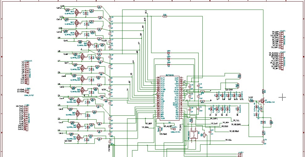
    Please find above AFE schematic for 12s connection.

    When i boot AFE by  giving volt> Vboot to TS1 pin.

    Following output i am able to get.

    Regout_Vss = 2.5v

    Regsrc_Vss = 10.1v

    VC5x_Vss = 13.5V

    TS2_vss = 13V

    CAP2_Vss = 13.7V

    VC10x_Vss= 28.3V

    TS3_Vss = 27.7v

    CAP3_Vss = 28.5v

    BAT_VSS = 44.9v

    CAP1_vss = 3.2v,

    Alear_Vss = 2.5v

    CAP3_vc10X = 300mV

    CAP2_VC5x = 300mV

    VC5x-Vss = 13.58v

    VC10x_VC5x = 14.75v

    BAT_VC10x = 16.61v

    I2c is also not responding.

    Request you to suggest inputs to turn on middle and top groups.

    Thanks

    Imran

  •  Hi WM,

    please find below the circuit diagram for 12s connection.

    on giving boot signal to TS1 pin (around 3.5v using a switch as per fig 8_3 of datasheet), lower group is turning on and cap1-vss is 3.2v

    But cap3_vss is 300mV and cap2_vss is 300mV.

    I2c is not responding and bus collision is occurring when AFE i2c is accessed.

    Regout = 2.5v

    Alert = 2.5V

    Request you to please suggest required actions for turning on top and middle group.

  • Hi Imran,
    While it is hard to see detail on the schematic, it seems TS3 and TS2 may be pulled to GND. The readings such as:
    VC10x_Vss= 28.3V
    TS3_Vss = 27.7v
    seem to confirm it. The part will not work with the TS3 and TS2 pulled to GND, they must pull to the local group reference, VC10X or VC5X respectively. See figure 8-3 in the data sheet.
    Also while it is hard to see detail, the power filter resistor for the BAT pin, Rf of the data sheet, it may be R16 or R14 at the top of your schematic, must come from the cell rather than VC15. You might check the VC10X and VC5X power filters also.
    The current source to the REGSRC dropping transistor should come from a low impedance source rather than VC10, typically the top cell of the stack to avoid imbalance.
  • Hi WM,

    Thnks for the reply. my friend raped the circuit.
    this will hlp.
    thnks
    imran
  • hi WM,

    It hlp. device started working.

    thnks
    imran
  • Hi Imran,
    Glad it helped and is working.