This thread has been locked.

If you have a related question, please click the "Ask a related question" button in the top right corner. The newly created question will be automatically linked to this question.

TPS55340: Frequency variation

Part Number: TPS55340

Hi 

Our customer ask the following question regarding the frequency and inductor.

 1. Could you provide us the variation of "41600" and "-0.97" at the following equation?


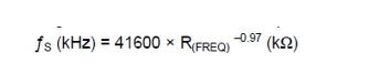
     Because the customer would like to estimate the variation of the frequency which is set by the resistor.

 2. Regarding the sub-harmonic oscillation, we are concerned the oscillation as it mentioned at the following section.

     How much is the inductor value can be avoided the sub-harmonic oscillation? Could you provide the equation to calculate for that ? 

Best Regards,

Koji Hamamoto

  • 1. This is not characterized. Instead, we provided the fs range at three different Rfreq values in the EC table. Hope this helps.
    2. Please refer to a power electronics text book for detailed info of slope compensation in current mode controlled circuit. The basic idea is, the down slope of the inductor current (namely when the main switch is off and the diode is conducting) should not be 2x greater than the injected slope. Most time people use 1x as the criteria in practical design. Note that the injected slope signal is in the form of Volt per second, and the actual inductor current slope is Amp per second, which times the current sense resistor, becomes Volt per second. So the current sense resistor also plays a role.

    Such slope compensation requirement sets the constrain for the inductor selection.
  • Hi Koji-San,

    PLease check my answer below:

    1. This  frequency formula is a fit formula from the test value. So we can't get the operation frequency tolerance from it. Please refer to the table on page 5. the tolerance is +-20% with a 1% precision resistor. +-20% has already consider the tolerance of the resistor.

    2. For the slope compensation, please refer to page 7.3.6 on page 11. Make sure Se>2*Sn. Generally, L>3.3uH can meet the target.

    What is the Vin, Vo, Io in your applicaiton? We can help on that.

  • Hi Youhao-san, Helen-san,

    Thank you so much for your support.

    Regarding #1 question, I understand we can see the tolerance at page.5. However our concerns is that each frequency has different tolerance. Why it has a different tolerance?  +/-20% looks smaller than the specification.

    Regarding #2, please let me make sure. To prevent sub-harmonic oscillation , we should be Se>2*Sn. in most case, L should be more than 3.3uH. Is that correct? 

    Best Regards,

    Koji Hamamoto

  • Hi Koji-San,

    Q1: The tolerance is due to the tolerance of the test error and the internal logic delay at different frequency.  Our sepc leaves very big margin . Generally +-20% tolerance is OK for this part.

    Q2: Yes, to prevent sub-harmonic oscillation , it should be Se>2*Sn.  Generally, L>3.3uH can avoid the problem. But it also depend on the operation frequency.

    Again, what is your Vin, Vo, Io? And what is your target frequency?

  • Hi Helen-san,

    Thank you for your support as always.

    Q1: ok, I will suggest the value to the customer.

    Q2: The customer's condition is the following two cases.

           Vin=2.9V, Vout=8V, Io=0.6A,

                  A):fsw=2MHz

                  B):fsw=450kHz

    Best Regards,

    Koji Hamamoto

  • Hi Koji-San,

    Thanks for the update!

    A) for the fsw=2MHz case, 3.3uH idncutor is enough, it will not cause nay sub-harmonic issue;

    B) for the fsw=450kHz case,  suggest  them use a 6.8uH-10uH inductor

  • Hi Helen-san,

    Thank you !
    I have new question. I will post to new one.

    Best Regards,
    Koji Hamamoto
  • Thanks Koji-San!

    Good luck!