This thread has been locked.

If you have a related question, please click the "Ask a related question" button in the top right corner. The newly created question will be automatically linked to this question.

TPS92512: TPS92512 current spiking at turn on

Part Number: TPS92512

I have the TPS92512 set up almost identical to the set up created by web bench except that

1. I and enabling the unit via 0-5v pulse into PDIM.  For the purpose of trouble shooting this is currently a constant 5v as soon as the micro powers up.

2. I have a thermistor set up to scale back the power if the board gets too hot.

Note: the system drives 3 parallel paths of 2 creee XQE LEDs

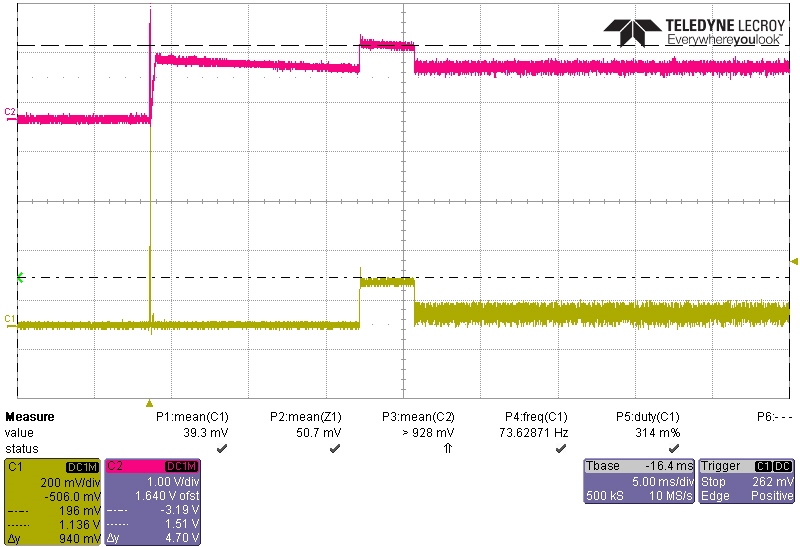
When I turn on the system I get a quick blip as shown below, the scope grab is measured from ground to pin 7 and is thus a current measurement. It appears for the first 20ms that the chip is stuck at 100% duty cycle and allowing for 5.6A of current, after that start up glitch it works properly limiting to about 0.3v at pin 7.  The glitch happens almost every boot cycle but varies in duration. Do you have any thoughts on what may be causing this?

  • Hello James,

    I have a few more questions:

    FYI I do not see a scope grab. Webench has a few options to optimize for, could you supply a schematic of this or at least the important part numbers and values?
    What is Vin, Vled (I assume about 6V), and Iled?
    How long does it take for the micro to power up?
    Can you look at COMP as it is powering up?

    Regards,
  • that's odd i had two images a schematic and a scope grab that showed up when i posted.

    Vin on my test is 15vdc

    Vled measured 6.9vdc

    ILED = 0.475A normally and 1.25A when it's in the goofy over current glitch. ( 3 paths of leds to triple those numbers for total current)

    The micro has control after 5.6mS

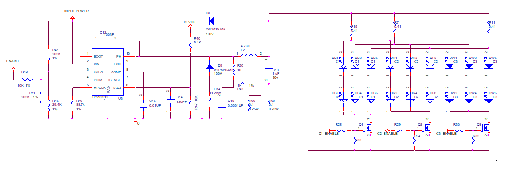
    If my post works there will be screen grabs below of the the current glitch, Comp pin in figure 2, De featured Schematic Figure 3.   I added a pull down resistor on the PWM pin to control it before the micro boots up. This appears to fix the problem.  So the micro before boot is tri stated, and the converter has a weak pull up so that means the converter is trying to turn on; but has a open on the output as none of the LED paths are enabled so no current should flow at that point.  Once the micro boots the converter and one LED path is enabled, this is where the high current occurs until some system on the converter goes back to normal.

    Figure 1: Input spike in current and normal current measured across a 0.41 ohm resistor in series with a LED path.

    Figure 2: yellow input system current across a 0.1 ohm resistor.  Pink V comp pin.

    Figure 3:

  • Hello James,

    So if you have no load attached and enable the TPS92512 the error amplifier will trying to provide more current until it reaches regulation. If there is no load it cannot so comp overcharges and when you enable the load the current will overshoot until comp brings it back to regulation. The pull-down resistor is disabling this until your micro powers up which will prevent this from happening.

    Regards,
  • Great thanks for the help.