This thread has been locked.

If you have a related question, please click the "Ask a related question" button in the top right corner. The newly created question will be automatically linked to this question.

TINA/Spice/UCC28951-Q1: UCC28951 as a boost converter

Part Number: UCC28951-Q1
Other Parts Discussed in Thread: TINA-TI, UCC28951, UCC28950, LM5046, LM5045, UCC2895, UCC3895, UCC1895

Tool/software: TINA-TI or Spice Models

Hello,

I am trying to design a isolated DC DC boost converter with the following specs:

Vin 18-36 Vdc

Vout 120 Vdc

Iout max 7.4A

I was looking at using the UCC28951 or UCC28950 for this, or possibly the LM5046.  Would one be better than the others for this application, I am not sure if the ZVS would help me or not?

Any suggestion on things to watch out for on TINA when trying to simulate a boost with these circuits?  I have been trying for over a day to simulate the UCC28950 to do what I need with no success. I am not able to get the part to act as a boost in any way, only a buck.  I started with the SLUSA16B reference design, which is a 410Vin to 20V output, so really the opposite of what I need.  Are there any boost reference designs, I havn't been able to locate any?

Thanks

Dan Buday 

  • Hi Dan

    The LM5046 is designed to run from a telecoms input and will run down to a 14V input. The UCC28950 can also work at this range but it is targeted at higher powers and is generally used on the secondary side of higher power designs running from 400V bus, normally supplied by a PFC front end.

    TI also has the LM5045 which is the a standard bridge controller designed for telecoms input voltage range like the LM5046, but no ZVS, as I tend to agree with you that ZVS is likely to bring little benefit at this input voltage range.

    There are PSPICE models and calculators for both the LM5045 and LM5046.

    Regards

    Peter
  • Hi Dan

    The main thing you will have to do is to change the transformer turns-ratio so that it matches the 18/36 to 120V conversion ratio. The transformer turns ratio in TINA-TI is specified as VS / VP so to get a 60% duty cycle at a nominal 24Vin and 120V out on a centre tapped secondary you should have a turns ratio of 16.6. For the centre tapped ideal transformer Vs is the sum of the voltages on the two secondaries (Vs1+Vs2 (I know that this is not the usual convention for turns ratio, but there you are !)

    You may also want to consider using a bridge rectifier output with a single winding - this will reduce the peak voltage stresses on the rectifiers but let's fix the basic 120V output issue first.

    Although the PSFB will work, you will find that the ZVS property of the PSFB is of little if any value at these low input voltages so a hard switched full bridge is an option.

    If you can't get the TINA file to work then you can email it to me and I'll see what I can do to get it running. I'm at colingillmor@ti.com

    Regards

    Colin

  • Peter and Colin,

    Thank for the quick response, I think I will end up going with the UCC28951, I think I will need the wider duty cycle range it allows because this supply will have to be able to switch to a 54V 7.4A output.

    Anyway, I went through and calculated all the values per the data sheet, but I still can't get TINA to give me anything beside 12V out.  This is the case even when I change the power transformer turns ratio and or the feedback divider.  I am attaching my simulation, I just modified the SLU277 reference design file. 

    Any help you can offer would be greatly appreciated, I am all out of things I can think to try.

    Parameter I used to calculate my values.

    Vin 18-36V

    Vin normal 28V

    Vout 120V

    Iout 7.4Amax

    Switching Frequency 100KHz

    Power Transformer Turns Ration 11

    Nominal Duty Ratio 60%

    Max Duty Ratio 90%

    slum277 working.TSC

  • Hi Dan

    OK - I've got your sim up and running - almost fixed as it were. Please note that I have made no attempt to optimise the sim, my only aim was to get it running to the point where you can start to play with it.

    There were a few things I had to do -

    The main one was to remove the 8.25k resistor at the SS pin

    I also 'fixed' the Vbias to 14V which is more reasonable than the 24V it was at originally.  To do this changed the DC level on VBIAS generator to 0V, there is a 12V superimposed on this which is why it was reaching 24V - the superimposed waveform is defined in the 'Signal/General Waveform dropdown box. I guess this was done to allow you to play with Vbias variations but I'm not sure

    There is some ringing on Vsupp that will feed into the CS signal - I thought that this was due to the input inductor so I removed it - but hte ringing is still there. It may be worth removing the common mode filter capacitor C13. Or else separate the input and output grounds. The sim won't like it if the two are floating but a high value resistor from Pri_GND to Sec_GND should allow it to converge.

    I removed the 8.25k resistor across the SS/EN pin - The controller is configured for Master mode and this resistor is not needed - in any case it should have been 825k and the 8.25k value was preventing the SS/EN pin rising past its 'run' threshold

    I also changed the SS cap from 150nF to 15nF - just to speed up the SS ramp - and made it even faster by setting the IC to 3V (don't do this on your real h/w !)

    I set the initial condition on the output capacitors to 120V (two places)

    I've changed the sim print time from 5us/5ms to 4ms/9ms - just to get the thing past the inital turn-on phase.

    I also added several voltage probes - you can delete them as you see fit

    Do tick the 'use initial conditions' box when starting the sim

    Here is the modified Tina Sim file - please let me know if it is running for you - if not then please re-open this thread and we can try to sort things out.

    Regards

    Colin

    /cfs-file/__key/communityserver-discussions-components-files/196/3414.1452.slum277-working.TSC

  • 2313.1452.slum277 working.TSCColin,

    Thanks for looking that over so quick for me and finding the errors I had.  At the times you set, the part does seem to work as needed, but the part itself doesn't actually seem to be regulating.  The output seems to go to 120V only because the output caps are set to 120V.  If I set them to 50V, 150V, 200V or 1000V the output goes to that value.  Also, I changed the load to 16 ohms to match my worst case output and the supply will just degrade toward 0V after the initial spike to whatever the output caps are set too.  Attached is your file with the output caps set to 200V and at 16 ohms load so you can see what I am seeing.  Do you think the issue is the transformer or the feedback network or something else.  I am assuming I calculated something wrong but I am not sure where to start looking, I must be making a flawed assumption some place that is throwing off my calculations.

    Thanks

    Dan

  • Hi Dan

    I haven't fully debugged the sim, there is still a significant high frequency oscillation on the transformer waveforms. However there is an error on the VOUTTP test point - it should connect to the output side of the output inductor (L1) not the input side - modified version below

    I'll work on the HF oscillation next to see what is driving it and how to 'fix' it.

    Regards

    Colin

  • Colin,

    Thanks again for all the help, I moved the feedback path to after L1.  After I moved that I played around with the output capacitor, output inductor, transformer turns ratio and the feedback divider, nothing seems to get the simulation to behave any differently.  Could there be an issue with the UCC28950 spice model?

    Thanks

    Dan

  • Hi Dan

    I'll check it out for sure. Certainly I saw the EA- input drop below the EA+ which was at 2.5V - I thought that was just because I did not let the sim run long enough. And there is still the issue of the HF oscillation on the transformer. I may be able to get to look at it tomorrow - I'm afraid I cannot get to it today

    Regards
    Colin
  • Hi Dan

    I think the model should be ok - I downloaded the original slum277 sim file this morning. It ran correctly with 12V out. I changed the output divider network from 9.09k to 8.08k and the sim then regulated at 11V.

    I'm still working on your sim - but it's a 'part time' activity due to other priorities.

    Regards

    Colin

  • Collin,

    Thanks again for any help, your helping me, so whenever you have time.  I am currently playing around with the UCC2895 part, its simpler but should do what I need, I'm just sure about the product life it seems older.

    Thanks

    dan 

  • Hi Dan

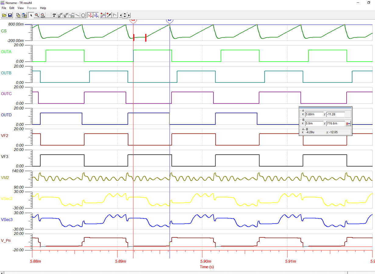
    I replaced the MOSFETs with voltage controlled switches that I can drive directly from the OUTx signals - this eliminates a lot of potential issues with the MOSFET models, gate driver transformer and gate driver ICs. I've also dropped Vin to 10V so that the system should run out to Dmax.

    I'm seeing  a delay between putting Volts on the transformer primary and the primary current rising (CS signal) - the time between the solid thick red markers below. I don't know why this should be there - I also reduced the shim inductor to 2uH.

    Anyhow, I think the next exercise would be to put in a current monitor instead of the CT - it will be tomorrow before I can get to that.

    As regards the UCC3895 - yes its an older device. It does not have the SR drives but you may find that with 120V out that SRs don't actually get you much improvement in efficiency. Its behavior in burst mode at light loads is not as well controlled. However, it may well be a good choice.

    I don't think that the issue you are having with the simulation is due to the controller - rather something going on in the power train. these problems may show up with the UCC3895 too.

    Anyhow - I'll keep you informed.

  • Hi Collin,

    Just wondering if you were able to look at this at all?  I have continued to play around with the last circuit you sent, but I have had no luck.

    Also, I would like to simulate the UCC1895/2895/3895 in LTSPICE.  Can you send me the unencrypted file for this, I see from other post that that is available per request for that specific part.  I need to start looking at other parts and their aren't a lot of options.

    Thanks

    Dan

  • Hello Dan

    The UCC2895 is still popular - it's listed as 'ACTIVE' so you should have no worries about continuity of supply. and Yes, - it is an older part. The UCC28950 added SR control and some burst mode features for added flexibility.

    I still have the question of why the schematic is not regulating at 120V out - I'm sure it's something simple but I'm afraid I have limited time to work on it - I may get to look at it this week but I cannot promise.

    Regards
  • Collin,

    Are you able to get me the unencrypted UCC2895 spice file, I would like to do the simulations in LTSPICE, I see that it has been given out to other people that have asked for it.

    My only concern with the 2895 is that this is for an aerospace application so we are talking decades of use not years.

    I can't justify the months and cost it will take to get a custom transformer as well as the cost of a prototype unless I can at least get a working simulation, so its important to me to get one of these two working in some form on any simulation tool.

    Thanks

  • Hi Dan

    Can you send your email address to me at colingillmor@ti.com

    I cannot post them here but I can send you the files.

    Regards
    Colin
  • Collin,

    Just wondering if you have had a chance to look at this at all?

    Thanks

    Dan Buday

  • Hello Dan

    I sent you my files a while ago. The open issue was that the system was not regulating at 120Vdc for some reason. I have not had an opportunity to debug the sim since then.

    Regards

    Colin

  • Hi Dan,

    Looks like this is continuing by email so I am closing the post.

    Regards

    Peter