Because of the Thanksgiving holiday in the U.S., TI E2E™ design support forum responses may be delayed from November 25 through December 2. Thank you for your patience.

This thread has been locked.

If you have a related question, please click the "Ask a related question" button in the top right corner. The newly created question will be automatically linked to this question.

USB-TO-GPIO: pinout confirmation

Part Number: USB-TO-GPIO

Team,

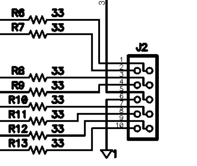
Can you confirm the pinout for the header for the card side. I want to make sure I get my signals out correctly


The data sheet for the tool list signals 1-10 and has a header shown in the EVM layout. Would the header on my card be the same ? I don't use ribbon cables often


http://www.ti.com/tool/USB-TO-GPIO

Looking down onto the card, how is the connector numbered? The first one like above?

  • The top drawing is looking from the bottom of the board, assuming the header for the cable is on the top.  And the second one is from the top.

    A good reference to use is that on our boards, pin 1 almost always has a square pad, while the rest are round.