This thread has been locked.

If you have a related question, please click the "Ask a related question" button in the top right corner. The newly created question will be automatically linked to this question.

LM3409HV: Output ripple not matching theoretical values.

Part Number: LM3409HV

I'm configuring an LM3409HV to be linear across voltage, and Analog Dim. I came up with values for the components that should produce results in line with what I need.

Please see attached spread sheet.LM3409HV_Experiment_330uH_60KRoff_0.22Rsns.xlsx

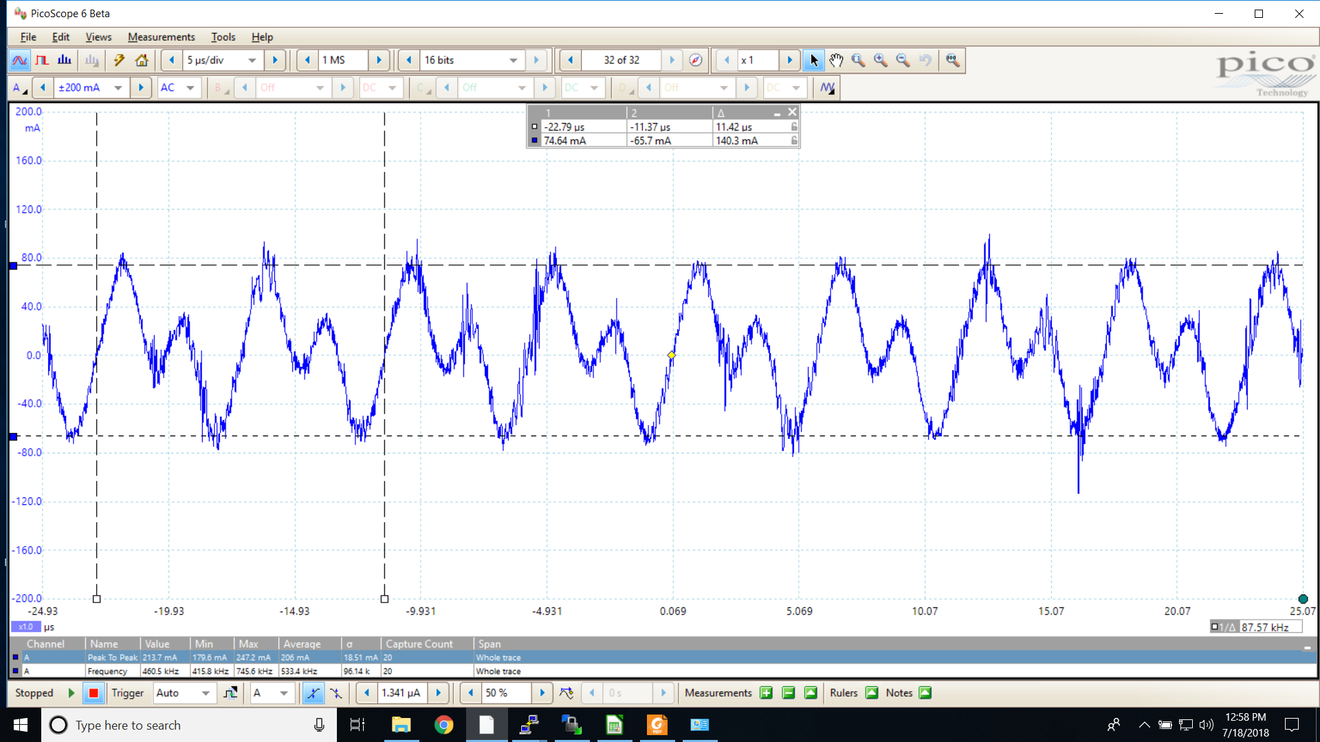
However, when I look at output ripple (example is 32V load 1.1 Amps approximately, IADJ is just above 1.24 volts), I'm seeing a ripple that is almost an order of magnitude bigger than what the math predicts.

You can see the component values I'm using in the excel spread sheet. The production version of this product uses different values and nicely matches the math.

Any ideas as to what I'm doing wrong?

  • Hello Brian,

    Just started calculating this but then looked at your data and calculations. It's not that far off (order of magnitude, less than a factor of two). Some of it is the alternating inputs to the error amplifier, remove that and you're about 100 mA peak to peak. Then a few questions: How did you get rD? rD can't be the same for all output voltages?

    Try removing Cout and see what the ripple looks like. Then you'll know if it's the converter or the capacitor isn't doing what you think it's doing. Ceramic capacitors value drop with applied DC voltage depending on the dielectric and how it's made. There are a lot of factors to look at when doing this type of calculation, for instance you are filtering a triangle wave so it's not a direct reduction as above. The delta I is fairly small so rD probably isn't changing a lot. Ceramic capacitor actual value with DC applied can vary. Switching frequency appears to be about 350 KHz, off but not that far.

    Regards,
  • Okay. Order of magnitude was too big. In fact it is: 0.140 / 0.023 = 6.1 times bigger than expected.

    I used a value I determined for a single fixture a while back... That was bad cheating and I'm glad you called me on it. That may account for the difference. I'm using 32-ish 1N4002 diodes, but I haven't found any data for the Rd of that diode.

    I did remove Cout to see if the ripple would match the inductor ripple calculations, unfortunately, the current became impossibly noisy and not measurable. The signal had high frequency impulses at every switching edge and ripple went to over 400 mA, if you included the high frequency impulses.

    The original circuit uses 100 uH, 20 K Roff, and 0.27 Ohm Rsns. When you calculate the ripple with those parameters you get around 20 mA worst case and it measures between 15 and 75 mA depending on current and voltage. Those values are much more representative.

    The ripple I show in the image, 140 mA, isn't worst case. Worst case is around 170 mA. When I'm driving 100 mA, the ripple is 71 mA which is way over the specification of most LEDs. Most specify between a 10% and 40% overshoot permissible.

    I'm trying to get the ripple down to about 10%, but alas I can't increase the frequency because of the LM3409HV rule you pointed out to me in another post. Delta I pp-min must be greater than 0.024 / Rsns, which is 109.1 mA, so 60 K Roff is as low as I can go unless I want the converter to go a bit wonky. I might try it lower anyway, just to see how unstable it becomes. I know the symptom, there are extra useless pulses from the converter and only every other cycle drives. That makes the ripple higher in some cases, although considering how different the two phases are, I'm not sure it's going to be much worse.

    Thanks for your help. Any suggestions would be greatly appreciated.
  • Hi Brian,

    Sorry was looking at the wrong row two above for some reason. rD is important and it's in the LED datasheet, see below for an example. Also, try the other direction, add another 0.1 uF and see what happens. I'm guessing not much since rD varies with current and it's probably much lower than you have in your excel. I looked at a datasheet that I have open and rD at 1A is around 1 ohm for one led, so it would be 8 ohms for 8 leds which is around a 30 volt stack overall for that LED. To get rD you have to look at LED dv and LED di centered around your operating point. The slope of that is rD for one LED. Example would be (3.7V - 3.5V)/(1200 mA - 800 mA) = 0.5 ohms (just an example). This is from the Vf versus LED current curve, also notice it's not a fixed value. rD will be much higher at low operating currents.

    Do you have a limit on how much capacitance you can have across the LEDs? 0.1 uF really isn't much and probably isn't doing much.

    Regards,
  • Thanks for the quick reply. I can't add any more capacitance. 0.1 uF Coff and 330 uH inductor is pushing my communications over DC to the limit as it is.

    I guess I'll have to start experimenting with higher frequencies to see what goes wrong when I violate the delta I pp-min spec.