Other Parts Discussed in Thread: TPS61089
Hi,
I am using TPS61098 to boost voltage from LiFePo4 battery (3.2V to 2.9V) to 6 volts to drive this motor: Thomas G6/02-8
The motor draws 0.5A - 1A of current
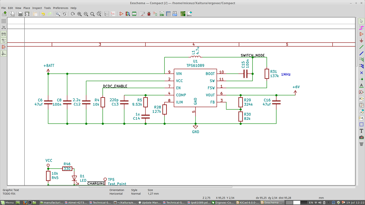
My schematics are below, the inductor I have used is COILCRAFT XAL4030-472MEB
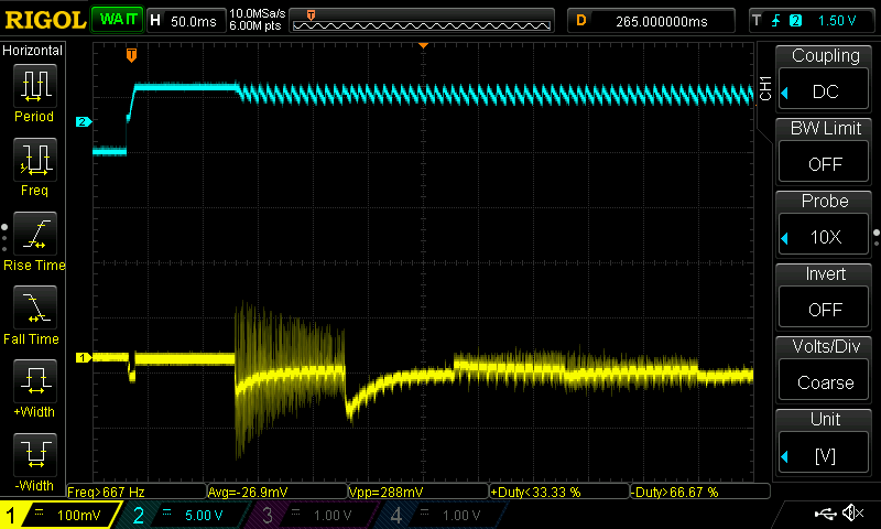
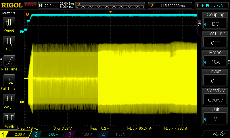
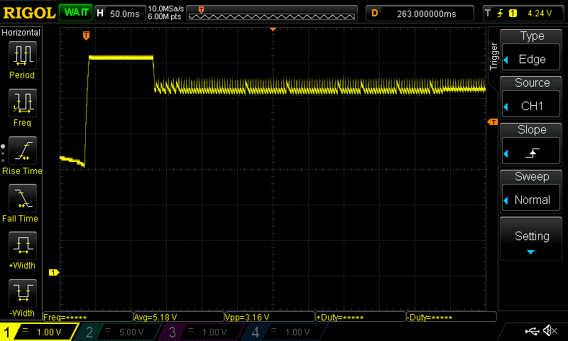
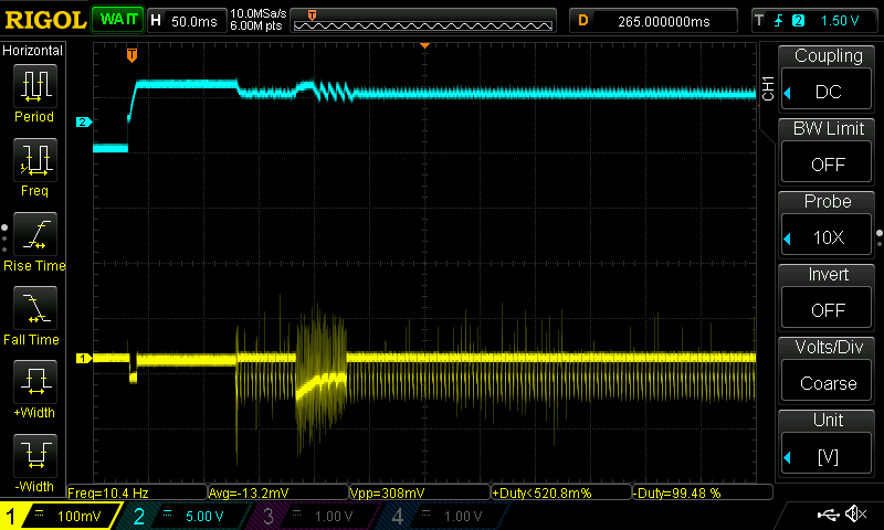
I have used webbench tool to design the circuit, values for compensation network were R5=9.53k, C14=4.7n and C13=220p. The circuit did not start at Vin=3.2V with these values. I have experimented and found out that changing C14 to 1u made the circuit start and power the load at 3.2V down to 3.0V, but failed to power the load at Vin voltages down to 2.8V. Then changing R5 to 1k made it work down to 2.8V. While this is fine, I feel that I am poking in the dark here.
I have made calculations based on formulas presented in the datasheet:
#Input voltage
Vin = 2.8

#Output voltage
Vout = 6

#Output capacitance
Co = 47e-6

L = 4.7e-6

#Output load resistance
Ro = 6/1

#Internal sense resistor
Rsense = 0.08

#Amplifiers transconductance
Gea = 190e-6

efficiency = 0.95

D = 1 - (Vin*efficiency)/Vout
print("Duty cycle " + str(D))

#right-half-plane-zero's frequency
Frhpz = (Ro * (1 - D)**2) / (2 * pi * L)
Fsw = 1e6
#Loop cross over frequency
#Choose to be smaller of 1/10 of fsw of 1/5 of Frhpz
fc=min(Fsw/10, Frhpz/5)

print("Frhpz = " + str(Frhpz))
print("Fc = " + str(fc))
R5 = (2*pi*Vout*Rsense*fc*Co)/((1-D)*1.224*Gea)
print("R5 = " + str(R5))

C5 = Ro*Co/(2 * R5)
print("C5 = " + str(C5))

Resr=0.003
C6 = Resr * Co / R5
print("C6 = " + str(C6))

---------output---------------
Duty cycle 0.556666666667
Frhpz = 39.93E3
Fc = 7.987E3
R5 = 10.98E3
C5 = 12.84E-9
C6 = 12.84E-12
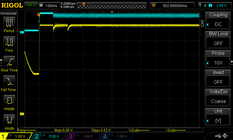
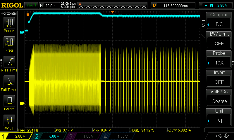
I have tried using these values with no luck - the dcdc converter seemed to start up and then quickly went into mode where it applies short bursts of PWM into inductor. This way the output voltage is not maintained at set 6V, but lower - around 5V.
Can someone please comment, what did I do when increasing C14 and reducing R5 drastically. Also where is the problem in the calculations? Is this related to motor being a complex load and Ro being 6V/1A is too big simplification? How do I go about properly calculating loop compensation component values? Am I safe with the values I have experimentally chosen?
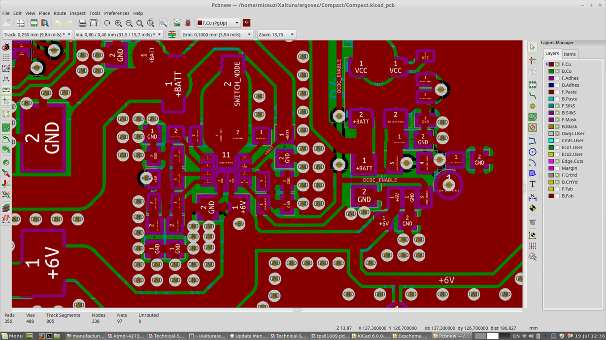
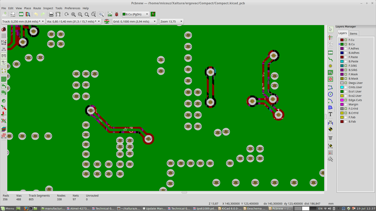
My layout is two layer:


