This thread has been locked.

If you have a related question, please click the "Ask a related question" button in the top right corner. The newly created question will be automatically linked to this question.

TPS61161 blows on LED disconnect

Other Parts Discussed in Thread: TPS61161

Dear sirs,

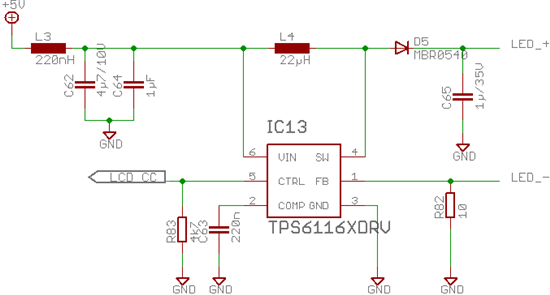
I have successfully implemented the TPS61161 to drive a string of 9 backlight-LEDs, using the configuration from the datasheet. But after having built 100 units, I have 5 ones on which the TPS61161 had to be replaced (and no component else). On two occasions the LED string FPC had been accidentally removed during operation, on the other times it had been removed before applying power. Since I have to revise the PCB and the IC should be Burn-Proof itself I would like to ask for hints why the IC fails when it should not. The IC is power from 5V, the signal LCD_CC is a PWM signal with an amplitude of 3.3V and a duty-cycle of 80% default. I can not find the dimming frequency striving through the linux-sourcecode but it has to be between 35kHz (most likely) and 4.3kHz (prescaled by 8).

When the device fails, the output is permanently on (Vin-0.15V).

Thank you for your ideas,

Guenter.

  • The TPS6116x family has an OVP circuit that should protect the IC in the event that the LEDs fail open or are removed.  Can you use an ohmmeter to measure the resistance from each pin to GND on one or more of the failed ICs, that has either been removed from your board or on board with all of the passive components removed?  Also, can you use a scope to capture Vin, CTRL, FB and SW pins when you remove the LED string (triggering on LED_+ going high?  Also, board layout on boost converters is critical, specifically you need to minimize the distance from SW pin 4 through D5 through D65 and back to GND pin3.  Bad board layout can cause excessive ringing on the SW pin. 

  • Thank you Jeff,

    looking through the datasheets of the passive components around, I saw that I have chosen a really bad replacement Inductor in my second BOM since I didn't get the original one anymore. Although I had error with both, can an Inductor with a too-low saturation current rating affect the shutdown protection?

    The components mentioned are placed as adjacent around the chip as their casesizes allows.

    On the fist occasions I tried to measure with a Ohm- and with a Diode- Meter for shorts/iriitating measurements, but no luck.

    Does the open-cicuit condition lead to temperature rise? Maybe it is a thermal fault? Under normal conditions I can barely measure a temperature rise (2-3°C w/IR-meter).

    Thank you for your time,

    Günter.

  • Yes.  The undersized inductor could cause damage to the OVP circuit.

  • Ok, thank you very much.

    So for my next batch i will use a Murata LQH44PN220MP0L (22uH@1MHz, 0.79A, 0.37 Ohms), enlarge the copper pad and >>> try again.

    Günter.