This thread has been locked.

If you have a related question, please click the "Ask a related question" button in the top right corner. The newly created question will be automatically linked to this question.

TPS54232: 12V to 5V buck converter has overshoot to 6.5V ad power-off switch bounce

Part Number: TPS54232

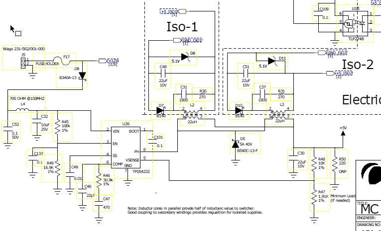
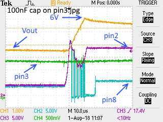
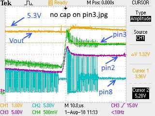
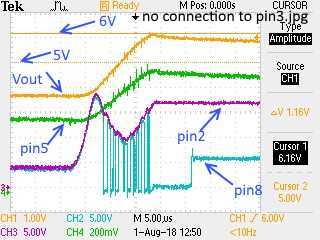
I have a TPS54232 12V to 5V(2A) design that overshoots to about 6.5V for 500uS when the power connector cable is disconnected (with occasional "switch-bounce").  I can see the feedback voltage start to drop as the power is removed, but as the bounce re-applies the power, the switch turns on for about 5us, and then the switching action continues for about 10 cycles over the next 8us.  the output voltage makes it to the programmed 5V after about 6us, and continues to rise until the switching stops, ending at about 6.5V.  My 5V powered BGA processor doesn't like this.

The datasheet (page 12) talks about the Overvoltage Transient Protection (OVTP) that is supposed to take effect at 109% of the programmed voltage.  I see a divided version of the output voltage on the sense terminal, so I would expect that the OVTP would stop the switching around the 6uS time (where the output voltage exceeds the programmed value).  Since I didn't find any threads on this topic, I'm either a pioneer, or just unlucky.  Any hints from users of this part?

I have seen a similar problem with the LM2676S part that was solved by using the LM22676S, which specifically did not have this problem.

Thanks,
Carl

  • hi Carl,

    I am looking into this question, and will give you feedback on Monday.

  • If you need more information, I have some scope shots of the problem. I can also share my schematic.

    Thanks,
    Carl
  • Hi Carl,

    Could you please upload the waveforms (Vin, Vout,Iout,SW)?

    Best Regards
    Shawn
  • Here are scope captures of the waveforms showing the problem:

    Each picture is labelled to show the trace-color net signal matching.  

    Yellow (Vout, 5V filtered output)

    Green (Vin, pin 2)

    Blue (SW, PH, pin 8, output drive)

    Pink shows pins 3 (EN), 4 (SS), 5 (VSENSE), and 6 (COMP) 

    A am not set up to measure the requested Iout.

    Please let me know if you need more information.

    Thanks,
    Carl

  • Hi Car,

    It seems the output voltage will increase to 6.5V every time, that is strange. Could you please share your schematic? I'd like to check if there's a problem in the schematic. And what is the load or next stage?
    Also, please check whether the startup has the same issue(increase the input voltage from 0).

    Best Regards
    Shawn
  • Here is the power supply schematic.  I think you can ignore the parallel dual-winding inductors, since they behave the same as a single 11uH inductor in this circuit.  The output does not always jump to 6.5V, but has to be carefully  teased to perform this action.  It occurs when the system is running and the power is momentarily disrupted (removed and then reapplied).  I do this bu wiggling the banana plug connecting the power to the power supply.  If the timing to provoke this behavior is important, I can rig up a calibrated interrupter and get that information.  You should be able to repeat the problem within a minute of connector teasing.  If you can't repeat it, can you send me a demo board and I'll return a modified system that will reliably repeat the problem.

    Thanks,

    Carl

  • Hi Carl,

    I will try to repeat this issue, and then give you a reply.

    Shawn
  • Is there anything I can do to help you to repeat the problem in your environment?
    Thanks,
    Carl
  • Hi Carl,

    Yes, I can repeat this phenomenon. But I think it is normal. This phenomenon only occurs when Vin increases from the voltage which is lower than Vout=5V. When Vin is lower than Vout, the device operates at 100% duty cycle, the Vcomp is very high, so it will take some time to response if Vin increases suddenly. If Vin increases from the voltage which is higer than 5V, the overshoot voltage will be smaller.
    You can improve your board from below two respects:
    1. increase the bandwidth to improve response speed, but you need to make sure the loop is stable. The overshoot will be smaller.
    2. change the UVLO, set the voltage to be higher than 5V so that the device will shut down when Vin is lower than Vout.

    By the way, why do you want to do this test?

    Best Regards,
    Shawn
  • I am not doing a test, but discovered this problem when a customer unit came back for repair. The 256-pin BGA had craters in the package. After removing the shorted BGA, I discovered that the power supply could be provoked into this overshoot mode. The 5V part's 6V absolute maximum specification is exceeded by this overshoot transient.

    section 8.3.10 of the datasheet discusses the built-in overvoltage transient protection, stating that the high-side FET is forced off if the VSENSE pin exceeds 109%. This should be at 5.4V. My captured waveforms show the switching continues past 6V.

    I am looking for a solution to this problem for future product builds and for possible field retro-fits. If this is the expected behavior of this part, can you be more specific as to your suggestions of remediation? Should I re-design my system to use a different regulator that does not have this behavior?

    thanks,
    Carl
  • Hi Carl,

    As I mentioned, you can set the UVLO voltage higher than 5V, so that the device will shut down before Vin dropping to be lower than 5V. You can try it to see whether this issue can be solved.

    Shawn
  • My UVLO (enable) is currently set to 8.6V in this design. My compensation was taken from the results of my WEBENCH design work. Does this change any of your recommendations?

    Thanks,
    Carl
  • Hi Carl,

    Please remove C132, this capacitor will affect the UVLO, 0.1uF is too large. Because the input voltage changes too fast, the EN voltage will not drop to UVLO voltage.

    Shawn
  • Removing that cap minimizes the overshoot problem.  I'm trying to understand why that cap was added to the design a year ago, and will try to address that issue in an alternate circuit change.  

    I'm surprised that the VSENSE limit was not enforced during this EN/UVLO condition, since the datasheet (8.3.4) mentions that the EN pin can be left floating.  I've attached 3 screen shots showing the results of the recent experiments, including letting the EN pin float:

    The first one is my original overshoot with the 100nF cap on pin3.

    The second one is the same settings with the cap removed (much less overshoot).

    The third one shows pin3 floating (no cap on pin3), but still overshooting. 

    You might want to add a caution about this condition in future versions of the manual.

    Are there any other changes you want me to try in my circuit?

    Thanks,

    Carl

  • Hi Carl,

    If you let the EN Pin float, the device will start up when Vin reach out to 4.2V, and shut down when Vin drop to 3.7V. So Vin is lower than 5V, the device will operate with 100% duty cycle. As I mentioned, if the Vin increase from this mode, the overshoot will be larger. what you need to do is preventing the device enter 100% duty cycle mode. So you need to set the UVLO voltage higher than 5V, so that the device will shut down when Vin is lower than 5V.

    In addition, from the waveform you captured, Vin changes too fast. I don't think the slew rate is large like this in the actual situation. Also, you can increase the input capacitance to lower the slew rate.

    Shawn

  • The additional EN information is good to have, and should be in the datasheet. That said, the VSENSE overvoltage protection (109%) should take precedence to protect the load from overshoot voltages.

    I have the wiring inductance (customer application power connections), connector resistance, a fuse, a diode, and a noise filter (Ferrite) in series with a 10uF ceramic cap to ground on the VIN line. My input power transitions are caused by "switch bounce" as the power connector contact is broken, so I have no additional control of the slew-rate of the applied voltage. This is the actual situation as the product is unplugged from a "live" motor-home.

    I think I can live with the results (after removing my 100nF cap on pin3). I'm suggesting that more information in the datasheet would be helpful. My biggest concern is that the VSENSE overvoltage feature does not seem to take priority of other housekeeping (startup, compensation, etc.) functions.

    Thanks,
    Carl
  • Hi Carl,

    Thanks for your suggestion, we will try our best to improve the quality of datasheet, and add more usefully information.

    Shawn