This thread has been locked.

If you have a related question, please click the "Ask a related question" button in the top right corner. The newly created question will be automatically linked to this question.

TPS54620: TPS54620 the inductance is buzzing

Part Number: TPS54620
Other Parts Discussed in Thread: TPS54331, TPS542941

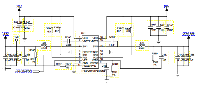
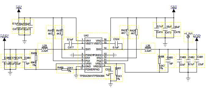
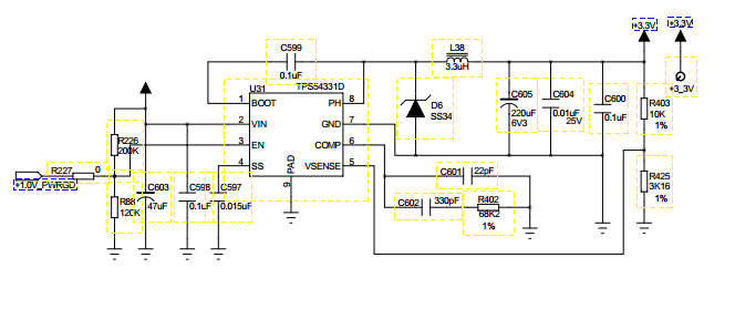
AS you see below,i use four power chip in my design ,the whole Power consumption of my board  is  8.54W when the board is powered  up ,now  there is a issue with my  board  ,when i  use  a  5V 2A power  to  power up the board,i find  the inductance is buzzing,then i find that the scope of +1.8V ,+1.0V ,the input +5V ,and the U31 output power is very bad。 They all has a periodic drop。i find the powergood signal of 1.0 V control +1.8V  and 3.3V of U31  .

AS you see belowi use four power chip in my design the whole Power consumption of my board  is  8.54W when the board is powered  up ,now  there is a issue with my  board  ,when i  use  a  5V 2A power  to  power up the board,i find  the inductance is buzzingthen i find that the scope of +1.8V ,+1.0V ,the input +5V and  the  output power 3.3V of U31 is very bad They all has a periodic dropi find the powergood signal of 1.0 V control +1.8V  and 3.3V of U31  .

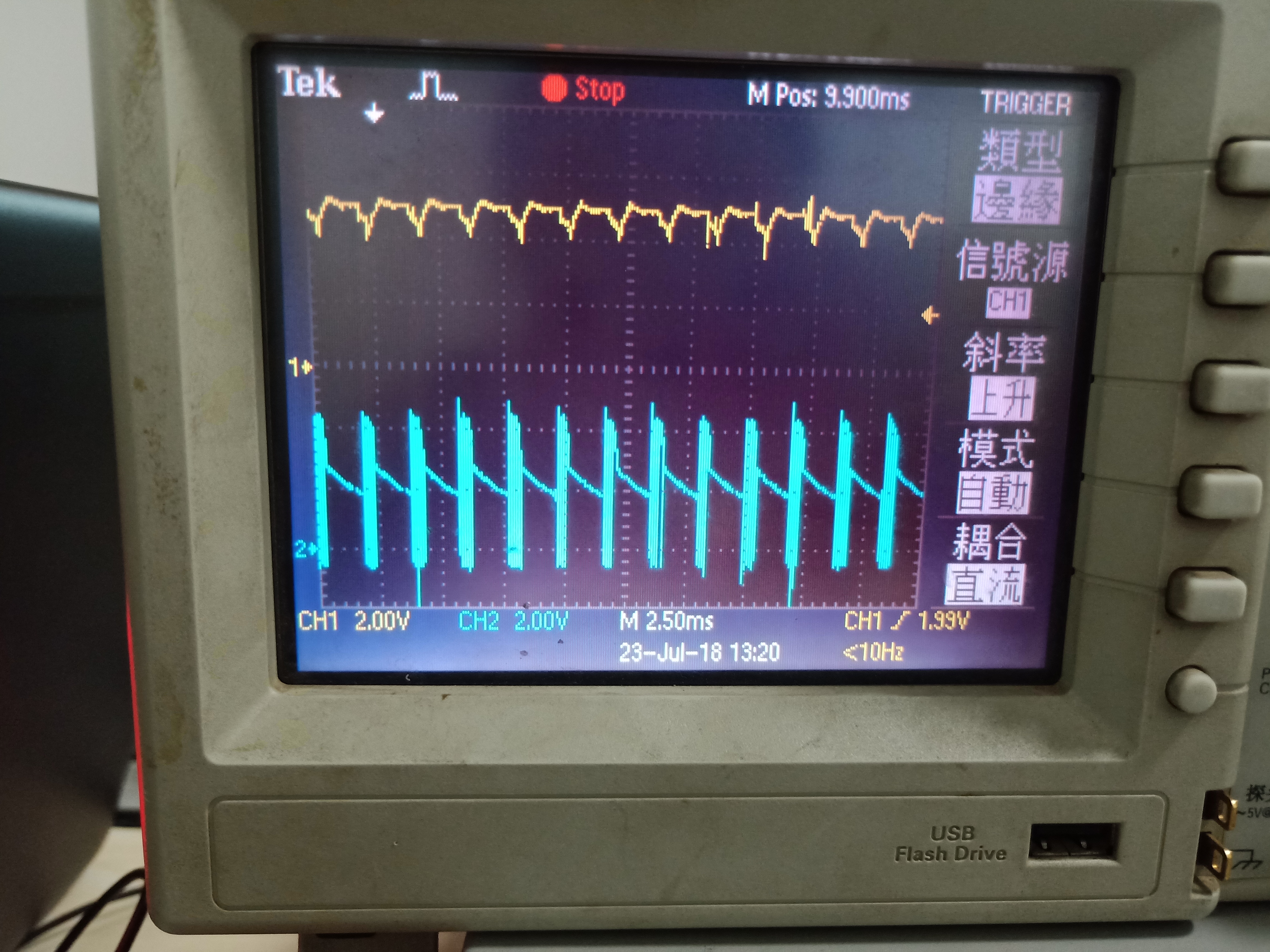
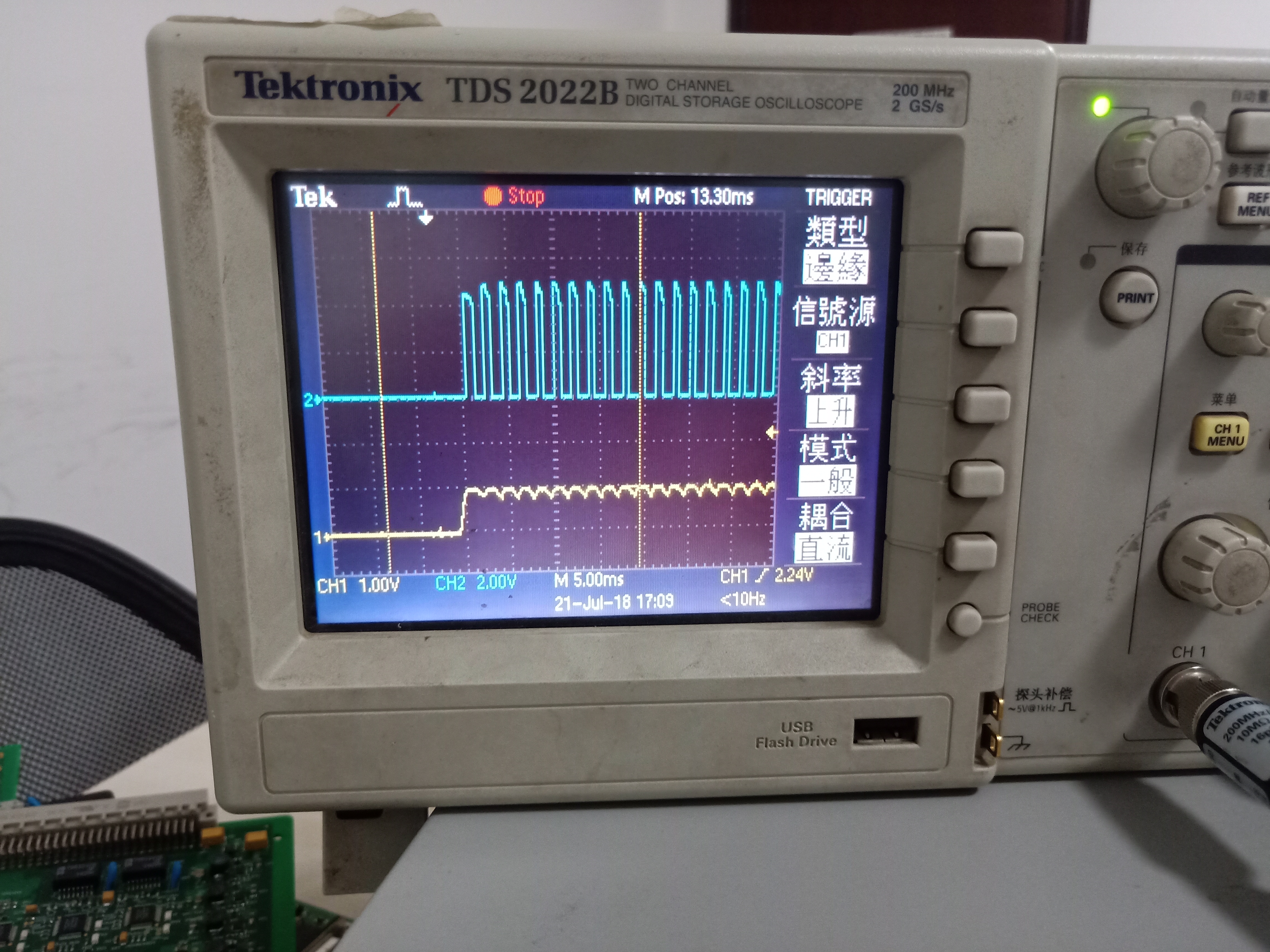
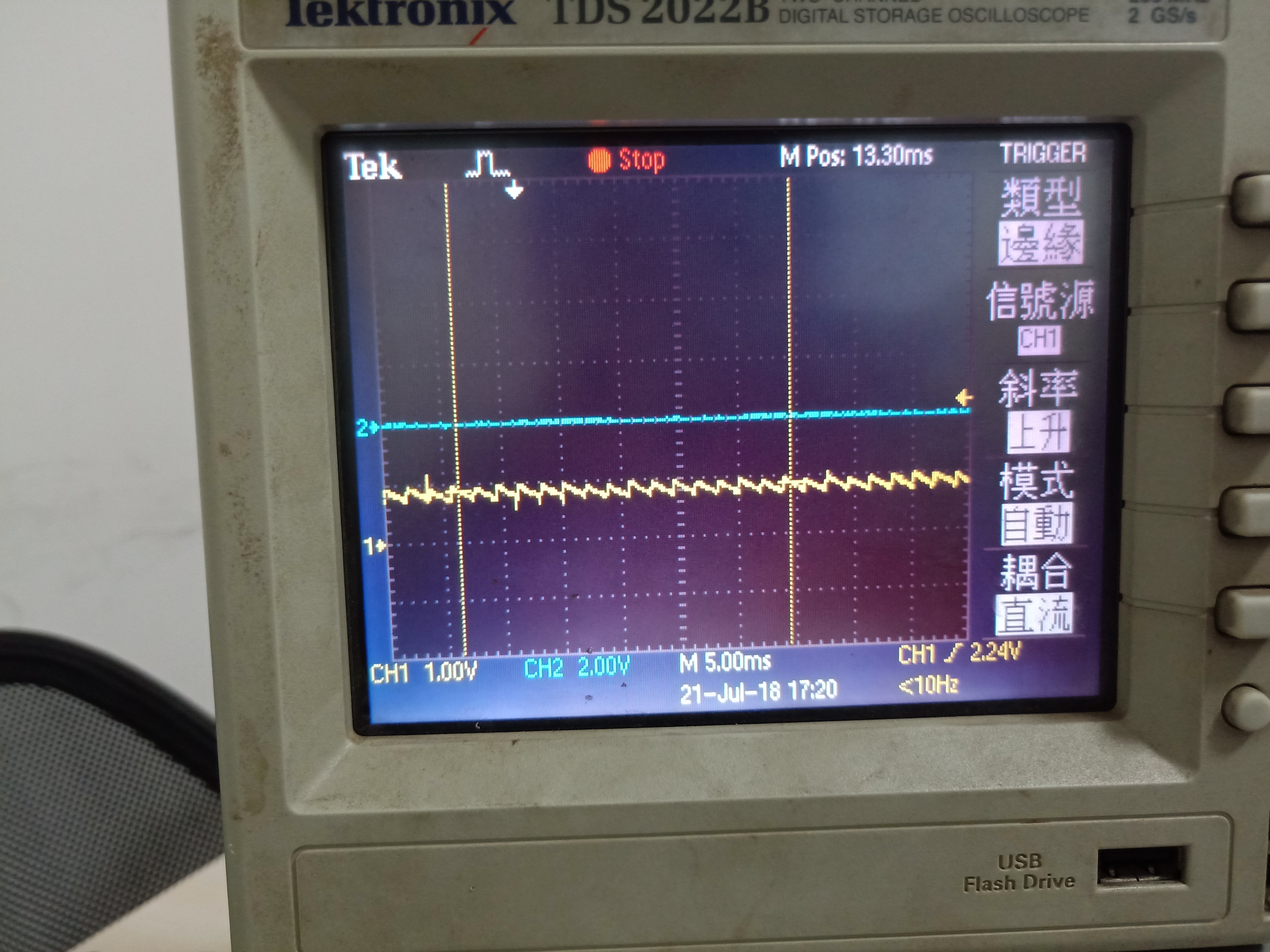
 so  i measure the 1.0 output and +1.0V_PWRGD signal when Inductive creaking, the pic as below the yellow is  1.0 output  and the blue is the othe one.


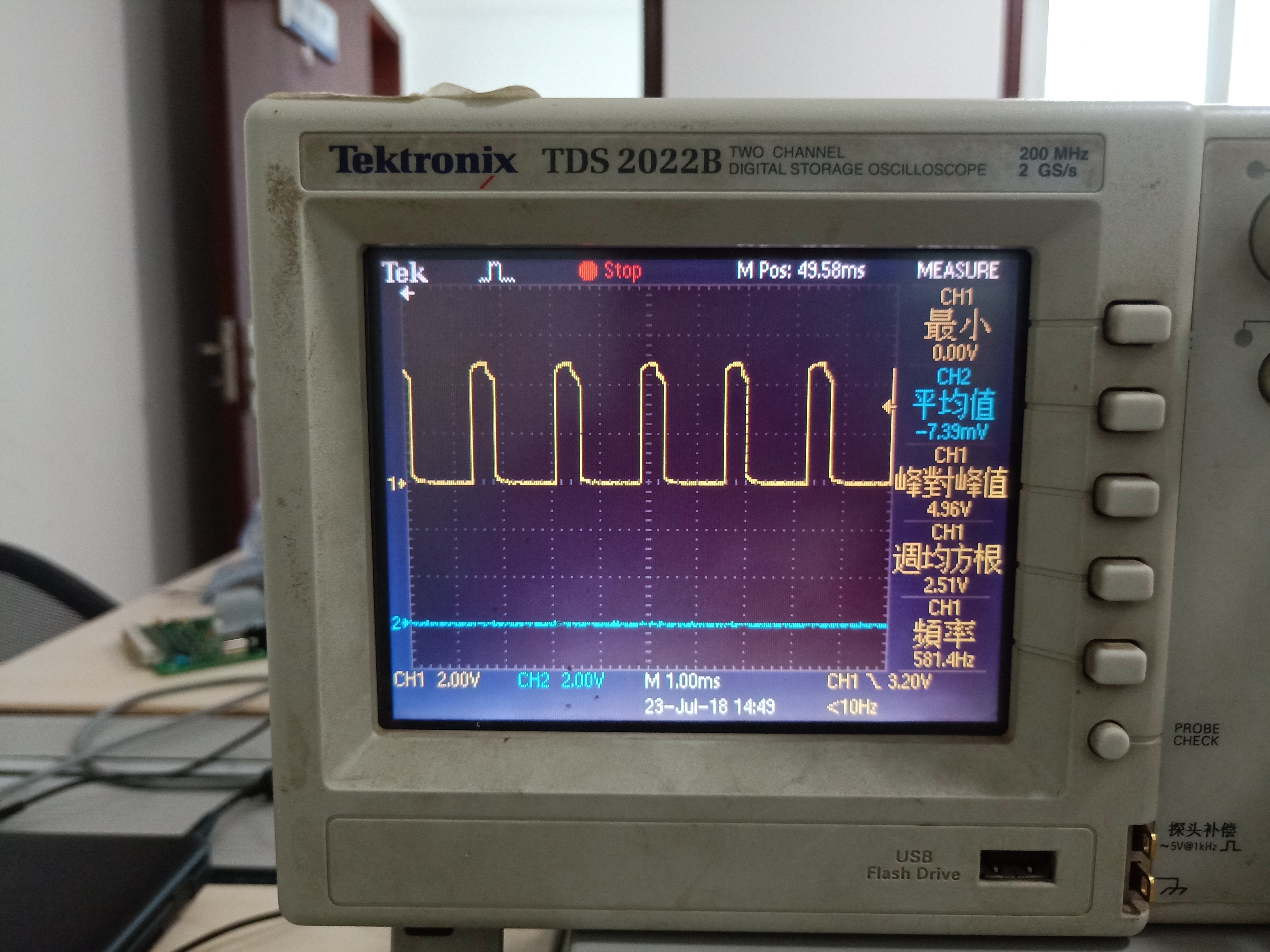
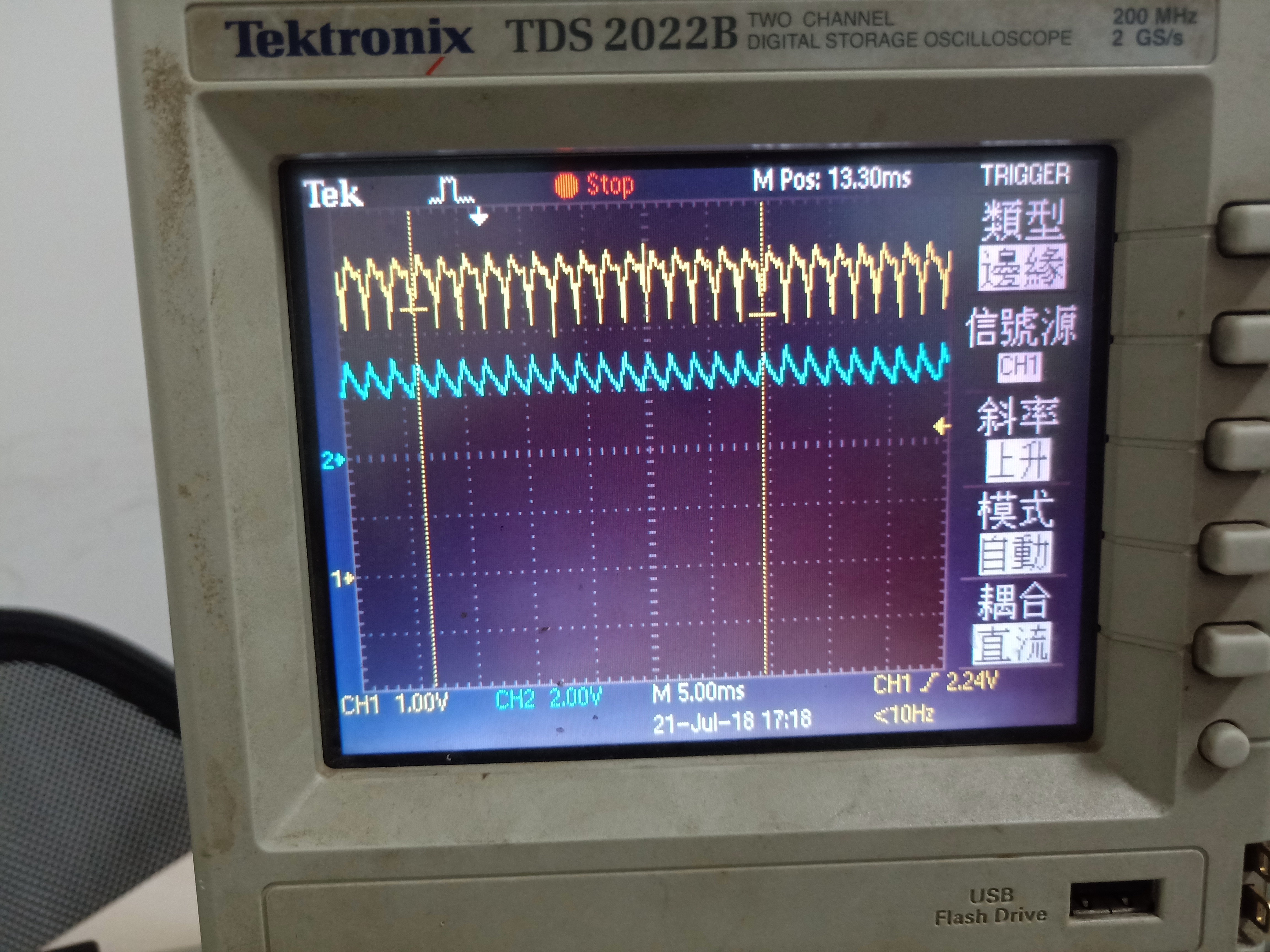
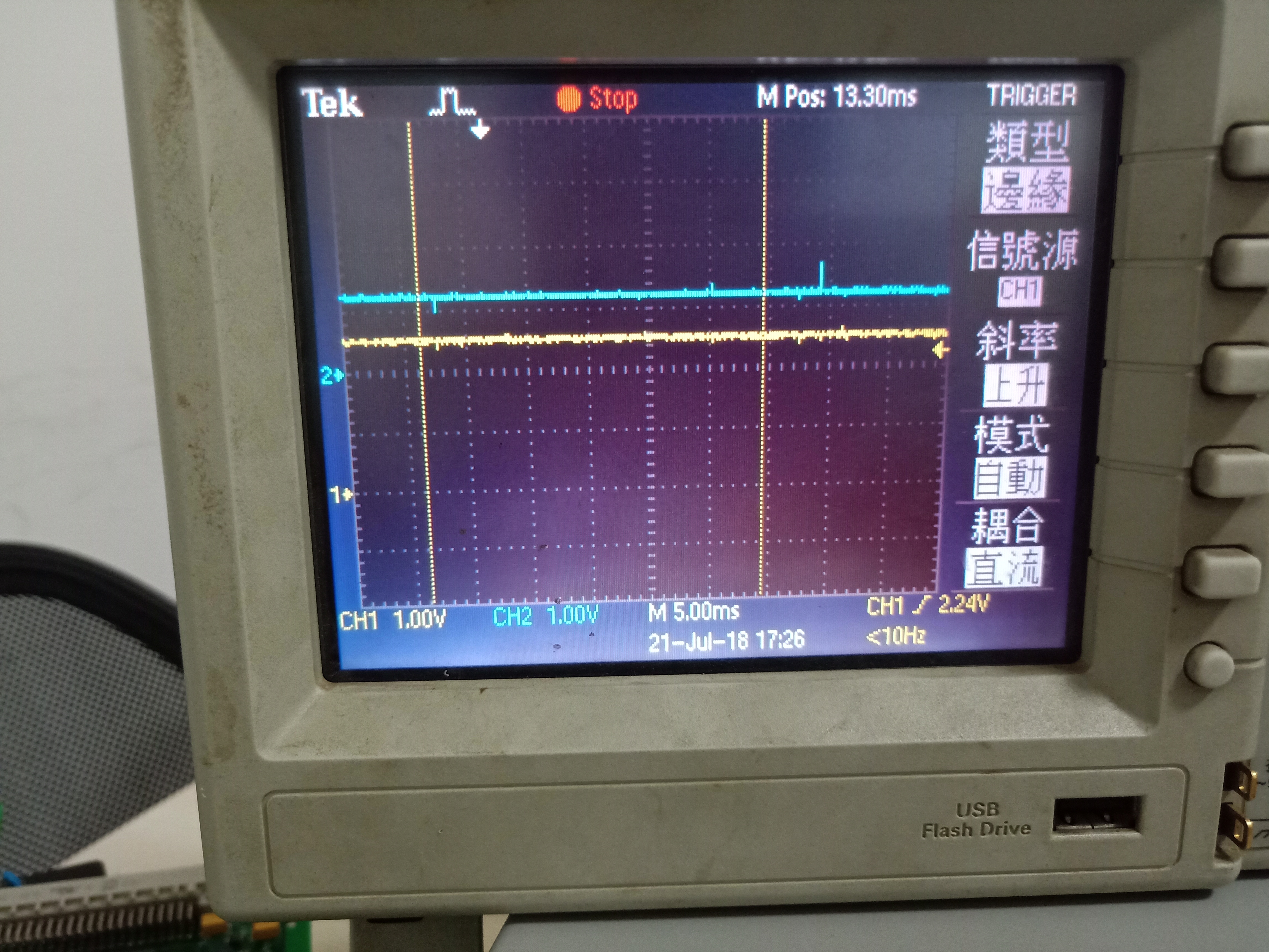
Besides,i measure the input power of the board +5v and the output 3.3v of U31 is as pic below

The yellow is +5v input ,and the blue is 3.3v output of u31.

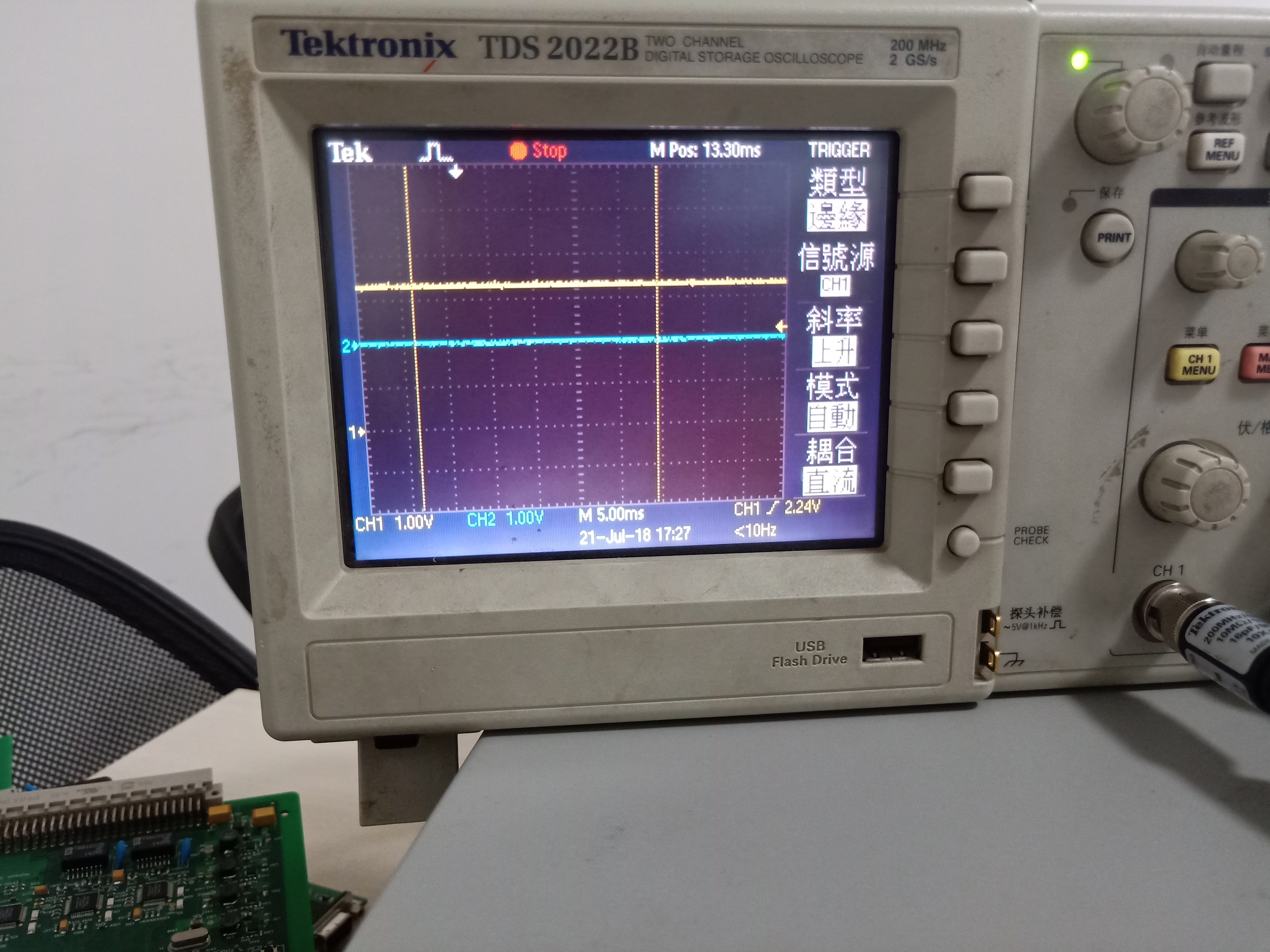
The pic below is 1.8V output of U41 ,


Besides the +1.8V ,+1.0V ,the input +5V and  the  output power 3.3V of U31 ,the othe power like +2.5v,+1.2v and +3.3V_SFP are all good .u can see below

 +2.5v&+1.2v

+3.3V_SFP

 All of pic above are measured during the inductance is buzzing and the board is powered by a 5V 2A power.

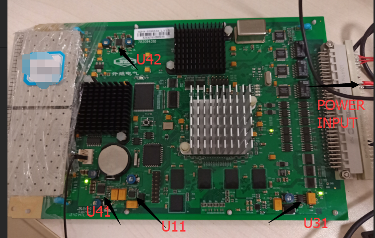
THE PIC of board is below


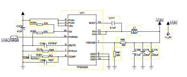
After I find this ,i have try to change C603 ,C370 to 220uf,

                                R301 of U11 from 1.2k to 12.1k,

                                L7 of U11 from 1uh to 4.7uh

                                L27 of U41from 2.2uh to 3.3uh

                                L38 of U31 from 3.3uh to 4.7uh

But it doesn’t matter.can somebody smart help me,Very anxious,

the problem of TPS54620.doc


  • User,
    It looks like your primary issue is with the 5 V input supply. It has over 1 V ripple and is dropping as low as 4 V. The input to the TPS542941 is very likely dropping low enough to activate the internal UVLO. That large ripple may be causing issues with the TPS54331 circuit as well. For TPS54331, can you zoom in at say 10 usec / div and show the PH node voltage as well as VIN? What happens if you increase the input voltage to 12 V? You may need to disable all the voltage rails and check them each individually. You are using devices supported by different groups within TI. It may be complicated to coordinate support for your issue.
  • hello john,i  find that when i change the input cap of U31 to 440uf( consist of 2 220uf cap) and the input cap  of U11 to 440uf( consist of 2 220uf cap) ,The inductance is no longer ringing.  pic  below  is  the PH node voltage as well as VIN of TPS54331 when  the inductance is buzzing. the yellow is VIN +5V,and the blue is the other one .besides, except the vin may drop to 4v and the the EN node voltage  TPS54331  whose pic is the second one ,may drop to 0V,I FIND THE other signal are all not undervoltage, exceeding the threshold voltage. so  i want to know wether The root cause of this problem is  the instability of the input voltage, which is reduced to 4V. and then  it casue the en EN node voltage  TPS54331 drop to 0V?

  • User,
    If your EN is going to zero V, the the circuit will shut down. you have 200 k and 120 K voltage divider fromVin. When Vin drops to 4 V, you would still have 1.5 V on EN. You also have a line connected to 1V0 power good.Maybe that is causing your reset. Another thing to look for is the TPS54331 BOOT UVLO. If the BOOT to PH voltage falls below 2.1 V and the load is light, the high side FET will stay off until Vout falls to Vin - 2.1 V or about 3.9 V as shown in your waveform. It looks like you have more than one issue to resolve, inclusing your poorly regulated 5 V input. where does the 5 V come from?
  • User,
    Did you ever resolve your issues? Do you need additional assistance?
  • I have solved my problem.The reason is that the input voltage is reduced to below 4V.I added a 600uf capacitor to the 5V input, and 5V is stable. I have never had this problem again.