This thread has been locked.

If you have a related question, please click the "Ask a related question" button in the top right corner. The newly created question will be automatically linked to this question.

LM2755: Schematic Review

Part Number: LM2755

Hi,

My customer would like a schematic review for the following:

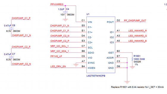
We plan to interface the LED driver with our MCU using 1.8V I2C logic. Can you verify that my schematic connections are correct?
1. SDA and SCL lines are pulled up to PP1V8_LP (1.8V) close to the MCU and not shown below
2. Is the VIO pin connected correctly?
3. We plan to use the driver at 30mA/LED and plan to replace the I_SET resistor with a 8.4k resistor. Let us know if you have any concerns with that.

Thanks,

Chuchen

  • Hi, Chuchen,

    The schematic has no problem and please also make sure "A pull-up resistor between VIO and SDIO must be greater than [(VIO-VOL) / 3mA] to meet the VOL requirement on SDIO. Using a larger pull-up resistor results in lower switching current with slower edges, while using a smaller pull-up results in higher switching currents with faster edges." is met.

    There is no problem to use 8.4k for ~30mA / LED.

    Please help to click "Resolve" if the problem is solved.

    Thanks.
    Regards,
    Kenneth