This thread has been locked.

If you have a related question, please click the "Ask a related question" button in the top right corner. The newly created question will be automatically linked to this question.

TPS61196: does not power up

Part Number: TPS61196


Hi

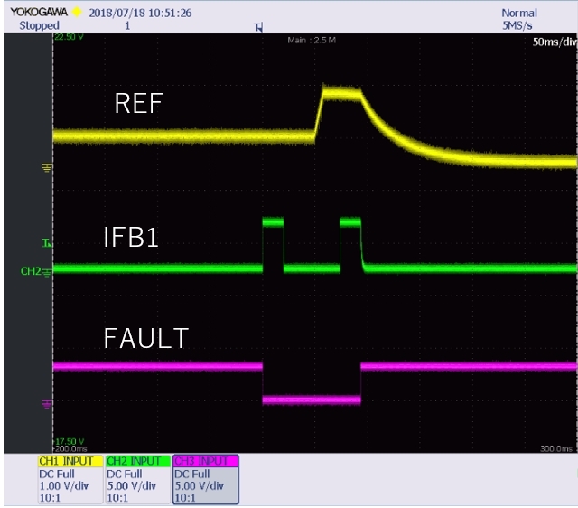
We have a problem when it startup. Please see the following waveform.

When we start up the device on the customer board but Vout does not goes up correctly. We repeat the startup then it operate finally normally.

When it does not startup, the FAULT signal become high.(Please see below)

Have you ever see this phenomenon before? Could you provide us the any causes which is possibility?

Best Regards,

Koji Hamamoto

  • Hi Hamamoto,
    What is your Vout voltage in normal operation. Please make sure under normal operation, the Vovp voltage, which is devided by resistors from Vout, is around 2.1~2.5V. lower than 2V will impact startup.
  • Hi Caryss,

    Thank you for your support.

    Vout is around 65V. And OVP divider is 3.9k(bottom) and 91k(Top). The phenomenon is occurred even if the OVP point is increased.
    Also other setting is below;
    ILED=60mA, VIFBV=0.308V, VLED_SHORT=5.86V

    Is there any concerns for the setting?
    And as you mentioned above, why Vovp lower than 2V impacts the startup?

    Best Regards,
    Koji Hamamoto
  • Hi Caryss,

    Vovp is not 2V. It is around 2.6V.(Please see above post)

    And I got new information for this issue. If Cout is decreased,the phenomenon does not occur.
    I had doubted the inrush current but the ISNS voltage does not exceed the current threshold.

    What should I check next?

    Best Regards,
    Koji Hamamoto
  • Hi Hamamoto-san,
    Can you take a try to change the resistor rating of the OVP devider resistors? Use 10Kohm as the bottom and calculate the related top resistor.
  • Hi Caryss-san,

    Thank you for the information.
    I had suggested that idea to our customer and they tried. However that was not resoled this issue.

    Please let me know if you have other idea. They can try it.

    best Regards,
    Koji Hamamoto
  • Hi Hamamoto-san,
    From the screenshot, it looks like the device hit the IFBx OVP after unused detection. what is the FBV voltage setting in customer design? what is the resistor connected from IFBx to GND in all the channels? Are all channels used?
  • Hi Caryss-san,

    Thank you for your support.

    > From the screenshot, it looks like the device hit the IFBx OVP after unused detection.

    Which waveform are you talking about? Can we talk by email?
    I have a schematics and layout also. I can share those information by email only.
    If it is ok for you,could you give me your email address?

    Best Regards,
    Koji Hamamoto
  • Hi Caryss-san,

    This is the answer for your question.

    >what is the FBV voltage setting in customer design?

    IFBV is 0.336V. (RISET=47kohm, RFBV=82kohm)

    > what is the resistor connected from IFBx to GND in all the channels?
    > Are all channels used?

    Yes. However IFB6 is an unused channel is connected 22kohm to GND from this pin.
    The other IFBx(1~5) ~ GND resistor is 10Mohm.

    Best Regards,
    Koji Hamamoto
  • Hi Caryss-san,

    I have one more question.
    As you can see at the above waveform, IFB waveform looks the open detection operated twice. Is this behavior correct?

    Best Regards,
    Koji Hamamoto
  • Hi Hamamoto-san,

    The open detection doesn't operated twice, the first one should be unused pin detection, the second one look like IFB ovp. 

  • Hi Caryss-san,

    Thank you.

    IFB OVP is 38V threshold. We already checked IFB1 voltage when it was shutdown as above. However it look not exceed the 38V.
    Please let me know if there is any pin voltage we should confirm.

    And if the one of IFB is unused, we just connect the resister to GND from unused IFB pin. Is this correct ? (On the customer board, unused IFB6 is connected to GND via 22k resistor)

    Best Regards,
    Koji Hamamoto
  • Hi

    The customer confirmed IFBx pin voltage as you mentioned, however it was not reached the IFB OVP threshold (38V).

    (IFB6 is connected to ground via 22k resistor because of not used.)

    What do you think?

    Best Regards,

    Koji Hamamoto

  • Hi Koji-san.
    What is the LED cross short protection voltage. This is determined by resistor on PIN ISET and PIN FBP.
  • could you please also test the COMP voltage in startup sequence?
  • Hi Caryss-san,

    I am sorry for the delay in my response.

    I got the waveform that is included COMP pin waveform.

    (20ms/div)

    Best Regards,

    Koji Hamamoto

  • Hi

    Could you follow the above question?

    Best Regards
    Koji Hamamoto
  • Hi
    In addition. The phenomenon disappear when Cout is decreased from 210uF to 110uF.
    However they need the reason for why this phenomenon appeared and also the permanent solution.
    Because the mass production schedule are approaching.

    Best Regards,
    Koji Hamamoto
  • Hi Caryss-san,

    I need your advice regarding  the following waveform.

    (Left: OK waveform,  Right: NG waveform)

    Q1: I do not understand why REF voltage is kept 1.25V when the startup fails. Could you give me any advice for the reason?

            Is there possibility that the startup fails when REF voltage does not rise to 2V?

    Q2: the customer does not use IFB6 channel. They connected IFB6 pin to the ground via 22kohm resistor. Should we left the pin open when the channel does not use?

    There are some phenomenon we do not understand why.

    Best Regards,

    Koji Hamamoto