This thread has been locked.

If you have a related question, please click the "Ask a related question" button in the top right corner. The newly created question will be automatically linked to this question.

LM5106: Min and Max of Dead time

Part Number: LM5106

Hi,

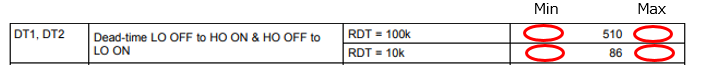
Datasheet shows that DT1 and DT2 are 510ns(Typ) at RDT=100kOhms and 86ns at RDT=10kOhms in 6.6 Switching Characteristics.

Q1: Could you let me know min and max value of dead time, please?
Q2: From Figure 15 and 16 information, I can't see "510ns(Typ) at RDT=100kOhms and 86ns at RDT=10kOhms"at 25 degrees.
       What mean does Figure 15 and 16 show?
       Why does this data have the difference between Characteristics and Figure15/16?

Best regards,
Shimizu

  • Hi Shimizu,

    Thanks for reaching out about this. Im an apps guy and will help out. This datasheet discrepancy seems to be an error in the EC table assuming the plots are correct. Let me double check this and update you asap.

    For the max deadtime check out this thread:

    For minimum dead time, there has been testing done showing 50ns DT can be achieved with RT = 1k however input pulses less than 50ns does not guarantee the output.

    Its also important to note that TI doesnt guarantee the datasheet parameters for using an RT resistor value thats not specified in the datasheet.  

    Let me know if you have any other questions and I will update you this error.

    Thanks,

  • Hi Jeff,

    Thank you for supoort.
    It is very helpful for me

    I add a question.
    Q3: Do you have a data of margin of error(min and max)?
           It means below red circle.

    Best regards,
    Shimizu

  • Hi Shimizu,

    To understand why the EC table is different from the plot figures:

    1) tolerance of the RDT resistor itself 

    2) EC value is a typical number and typical numbers will vary part to part.

    Of course the other reason could be the difference in the setup or even difference in the design typical v/s test typical.

    The plots should be able to be used to get the general range of min and max values and when compared to the EC spec the typical part to part variation can be realized. Does this make sense? Does this answer your question?

    Thanks,

  • Hi Jeff,

    Thank you for supoort.
    I add one more question.

    In datasheet of "6 Switching Characteristics", Test condition is RDT=100kOhms and 10kOhms.
    Could you let me know the margin of those resistor error value at test, please?

    I must show margin of DT to my customer.
    If this data can get, I will be able to close my customer's issue.

    Best regards,
    Shimizu
  • Hi Shimizu,

    I see thanks for letting me know this. let me look into this issue and update you asap.

    Thanks,
  • Hi Shimizu,

    When you say margin, are you referring to RDT tolerance?
    The part to part variation can be seen by comparing the typical from EC and 25C from plot.
    The resistor variation can be seen as the span (min/max values across temperature) of the plot
    and the resistor tolerance from the char test circuit is likely to be 1%

    Does this help?
    Thanks,