This thread has been locked.

If you have a related question, please click the "Ask a related question" button in the top right corner. The newly created question will be automatically linked to this question.

UCC24612: UCC24612 for current doubler rectifier topology

Part Number: UCC24612

Dear TI team,

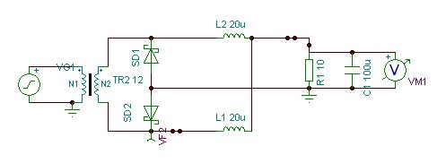
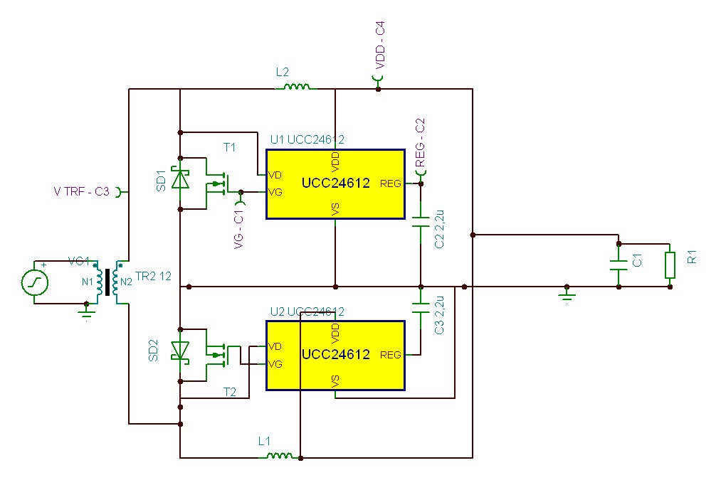
I tried to use the UCC24612 in a current doubler synchronous rectifer topology, but it doesn't work.

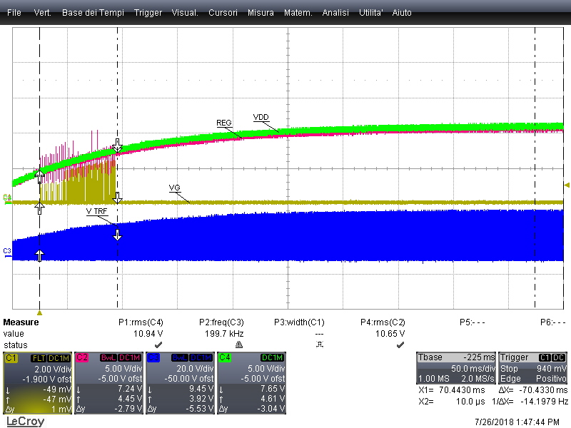
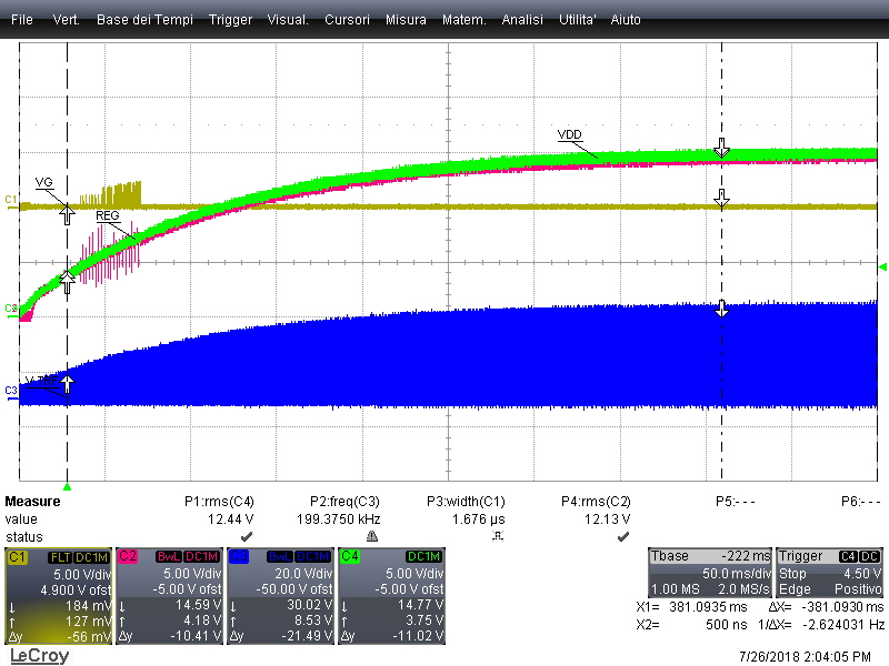
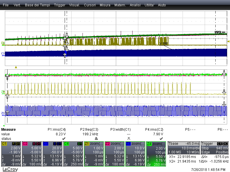
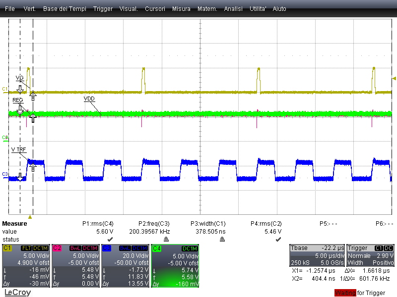
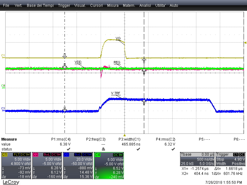
It seems to start producing gate pulses for a limited time interval at startup ramp, when the output voltage exceeds the 4.5V as stated in the datsheet.

Some milliseconds after no more gate commands are provided to mosfets.

Is it related to the rectifier topology?

Could it work in a full wave rectifier topology?

  • Hello Simone,

    Thank you very much for your interest in UCC24612.

    I would like to know the following for a better understanding of your application:

    1. What is the voltage on REG and VDD when the controller stops generating Gate drive. Looking at the waveforms will be helpful.

    2. How much current is your rectifier topology is feeding into VDD and if it is within the limits as mentioned in the datasheet.

    Given that the controller stops producing gate drive will suggest me that a fault is triggered, knowing the above two information will help me identify the fault.

    Regards,

    Sonal

  • Hello Sonal,

    thank you for support and prompt answer. I hope that the following details will be useful to understand what happens.

    Here's the circuit with the indication of the scope probes :

    Following the first panoramic screenshot. During Ramp up at about 4.5V on VDD and REG, VG begin to produce pulses.

    After some tens of ms, when VDD and REG are at about 7V, it stops working.

    I note that the voltage signal on REG suffers many spikes during the active period.

    :

    The Voltage on REG pin does not saturate its value to 9.4V but continues to follow VDD value..

    Zooming in it seems that some kind of burst mode is occuring during the active period.

    Focussing on gate pulses I note that not all of the positive polarization of the mosfet body diode  are "asserted"  by the VG pin. Moreover, the single gate pulses are stopped much before than the duration of positive polarization.

    It also seems that spikes on REG pin are dip caused by the gate pulse.

    I hope this is enough.

    Thanks in advance,

    Kind Regards,

    Simone

  • Hello Simone,

    I think we should look at what is causing the Vreg to drop through waveforms. Looking at the schematic your design looks alright to me.
    One way of approaching is to disable the half of your circuit and just run the sim with one controller to see if you are achiving operation with it before integrating the two togather.

    Sonal