This thread has been locked.

If you have a related question, please click the "Ask a related question" button in the top right corner. The newly created question will be automatically linked to this question.

BQ76940: AFE burning after a period & Cell Voltage Measurement Problem

Part Number: BQ76940

Dear all,


We are facing serious problems with the bq76940 due to chip burns after a random period.

In addition, the reading reported by the chip is different from the measured in several cells.


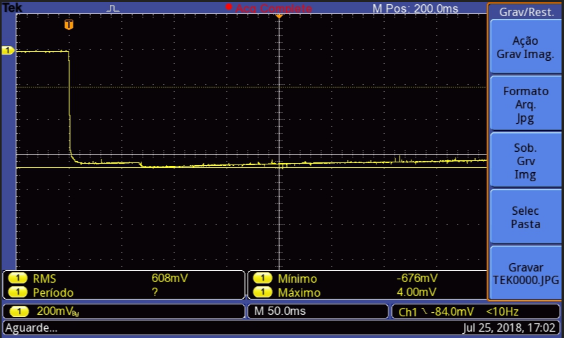
We believe that this problem is being caused by a negative voltage generated between the pins that causes some damage to the AFE.

In the case below, we show a measurement made between VC10x-VC15 during the connection of the first cells (C1-C5) without the presence of bq76940:

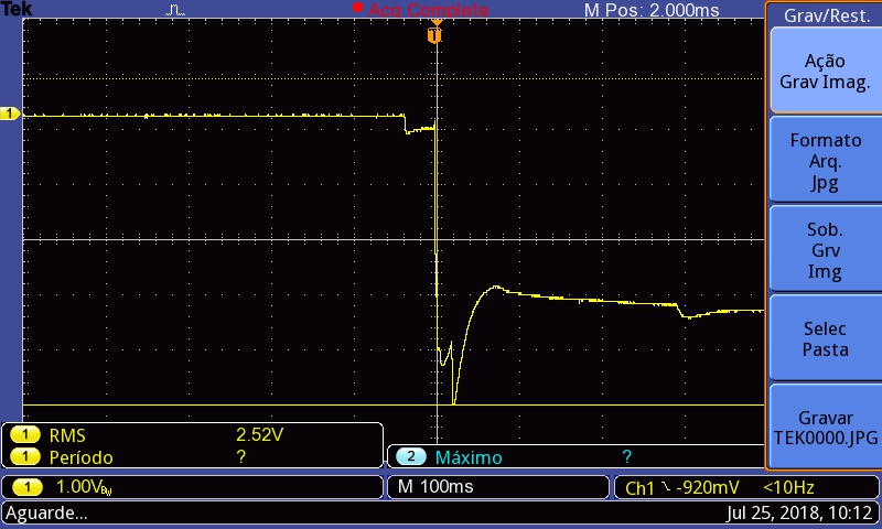
It’s worth mentioning that we don’t know if this negative voltage is the cause of the problem.


How can we solve this problem? What would be the suggestion to work around this?


Attached is the schematic of our BMS.

BMS Schematics 1.pdf


Best regards,

  • Hi Mauro,
    I don't see a problem from the schematic. The schematic looks very much like the EVM which worked, so your board would be expected to work also.
    It seems odd the waveform is so fast to fall. There are a lot of series capacitors pushing up VC15, they are in series , but the balance FET capacitance and 12 ohm resistors are also pushing up the unconnected cell inputs, and the power filter caps C701 and C713 should also be pushing up C15. With the bq76940 in the circuit there is an effective diode from VC10X to VC15, so -3V would not be tolerated well. The diode would conduct, current is limited by external components, but if the board is forcing that voltage the part may not survive. The circuit is expected to take an ESD event rather than sustained current.
    The connection of C0 to GND is not shown on the schematic pages. Since VSS is the reference for the IC GND is recommended first.
    What voltages are incorrect and what area or pins are burning may provide clues to the problem.
  • Hello, WM5295. Please find the answers below:

    Do the voltages appear correctly if all cells are attached?

    At the first moment yes, but after a certain period the voltages start to drift, mainly in group (C10-C15).

    In this case below, the error is in the voltage measurement of the cells C11 and C15.

    Is it one board with the problem or several?

    We had the same problem in 3 different PCB’s.

    How is the cell 0 connected to GND?

    C0 and GND are connected as shown below:

    What voltages do not report right, and what burns?

    It is mainly in the group of the cells from C10-C15. But we've already had problems with other cells.

    Does the board work properly at board test with power supplies or a resistor cell simulator then fail at/after cell connection?

    We are only using real cells. We are not using power supplies or cell simulator.

    We got two different results measuring between VC10x-VC15. First, the bq76940 was not welded to the PCB:

    Second, bq76940 welded to the PCB. Here we can see the internal diode acting.

    In order to protect the filter capacitors and the inputs, we placed zener diodes to each input as shown below:

    We left one board running for the whole wekend logging the cell's voltage provided through I2C. 

    Please see below the behavior of the voltage measurement:

    Do you have any recommendations or suggestions that we can solve this problem?

    Regards,

  • Hi Mauro,
    The bq76940 will have a diode like characteristic between VC10x and BAT, so the picture makes sense as you indicate.
    The incorrect voltage you will be able to see better, but from the picture it looks like cell 14 is falling low while cell 15 is rising. This is typical of a high impedance or intermittent connection to cell 14. When VC14 is connected to the cell through the filter network voltages read normally, when the connection comes loose the VC14 voltage falls causing the cell 15 reported voltage to rise and the cell 14 reported voltage to fall. You might check for contamination on the connector pins if used, or check the solder quality. If a harness is used for cell connection check for broken wires or poor solder or crimps in the interconnect. Losing power (BAT) can also affect the top voltages but it would seem odd for cell 15 to rise.