This thread has been locked.

If you have a related question, please click the "Ask a related question" button in the top right corner. The newly created question will be automatically linked to this question.

TPS65218: About DCDC5/DCDC6 is turned off issue

Part Number: TPS65218
Other Parts Discussed in Thread: AM4376, ,

Hi SIr 

We used TPS65928 D1 version to work with AM4376

We found that the PMIC cannot work well if VCC_5V_PMIC power is dropped down and then recovered.

Below is the photo 

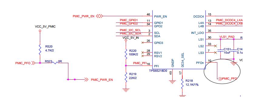
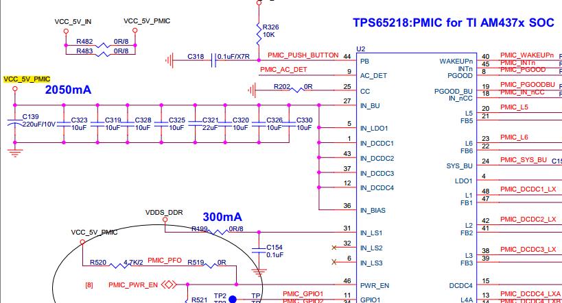
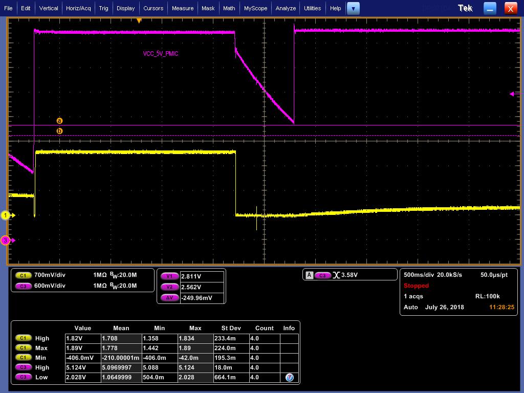
             1. VCC_5V_PMIC is the power of PMIC. The yellow signal is  PMIC_PWR_EN which is connected to CPU's RTC_PMIC_EN pin.

             2.  VCC_5V_PMIC is dropped and then recovered back

             3. and then DCDC5 channel and DCDC6 channel output are always 0.

Please advise.

BR

Yimin

  • Yimin,

    You do not have a Coin Cell backup battery connected to CC pin, so DCDC5 and DCDC6 will turn off when the IN_BU power supply is lost.

    The good news is it looks like PMIC_PWR_EN is pulled low by the processor very early by the processor. This means the power-down sequence should have been followed correctly.

    In the screen shot of your schematic, I cannot see the connection of AC_DET (net named PMIC_AC_DET).

    The datasheet says on page 43 "In a non-portable system, the AC_DET pin may be shorted to ground and the IC powers up whenever
    system power is applied to the chip".

    If AC_DET is shorted to GND, then the PMIC should shut down when VIN_BIAS falls to less than 2.7V (minimum) and the PMIC should power-up automatically when VIN_BIAS rises to greater than 3.1V (UVLOHYS = 1b = 400mV).

    If you refer to VIN_BU spec, DCDC5 and DCDC6 should continue to operate until your power supply is less than 2.2V
    Figure 5-18 shows that VIN_BU will supply SYS_BU (and DCDC5, DCDC6) until input and VINT_LDO drop below 2.5V, but your power supply never falls below 2.5V and this is only true when FSEAL == 1b (for systems with back-up coin cell batteries).

    It is my opinion that you are in the PRE-OFF state and DCDC5 and DCDC6 sequence down with the rest of the DC-DC converters, according to Figure 5-34. Modes of Operation Diagram. And because your system input voltage never falls below VIN_BIAS UVLO of 2.7V, then it never reaches the POWER_DOWN state.

    According to the diagram, DCDC5..6 should turn on again when (VIN_BIAS > 3.1V) && (AC_DET == Low) and the PMIC will be in the WAIT_PWR_EN state. If AC_DET is not low, this is my explanation for why DCDC5 and DCDC6 will not turn on.


    To test if your system is actually stuck, you should press the Push-Button connected to PB pin. This will force it out of the PRE-OFF or OFF state.

    In your schematic it appears PB pin is pulled up to some input voltage but also tied to GND through a capacitor, which creates an RC time delay. Why was this RC delay added and why wasn't a physical push-button included in your design? A physical push-button is useful in preventing issues in corner cases even when a battery is not used.
  • Hi SIr 

    thanks for your reply. and refer to your description as below 

    According to the diagram, DCDC5..6 should turn on again when (VIN_BIAS > 3.1V) && (AC_DET == Low) and the PMIC will be in the WAIT_PWR_EN state.

    If AC_DET is not low, this is my explanation for why DCDC5 and DCDC6 will not turn on.

    After checking my design, the AC_DET is connected to Ground. So the PMIC is in the WAIT_PWR_EN state ? 

    please advise 

    BR

    Yimin

  • Did you press the push-button (or connect PB pin to GND manually) to see what happens?
  • The problem seems to be the C139 220uF electrolytic capacitor at the input of your design (connected to IN_BIAS and all other IN_xxxx pins on the TPS65218D0 PMIC.)

    This capacitor is marked DNI on the TPS65218EVM-100, and should be marked as DNI on the AM437x reference design. 

    With a very large bulk cap at the input, it is relatively easy to create a scenario where VIN falls to the UVLO threshold and recovers just as DCDC5/DCDC6 are turning off. This means the PMIC ignores the new edge of the input voltage. But without the very large bulk cap, this scenario is difficult to reproduce.

    Even when the PMIC does appear to be locked up, pressing the physical push-button (connected to PB pin) always recovers the system (DCDCs sequence on) and the nWAKEUP pin is held low for approximately 20ms. The nWAKEUP pin from the PMIC tells the processor to drive the PWR_EN pin high.

  • Hi Sir

    When we shorted PB to ground, it can woks normally. It also works when we pull up the PWR_EN.

    So we think it should be in Pre-off status.

    And we will remove the C139 and try again.


    BR
    Yimin

  • Hi SIr 

    We have removed C139 220uF cap, but it doesn't help.

    The system cannot power-on, because VIN_BIAS never falls to less than 2.7V (minimum). It should be in Pre-off status when Vpfi< power-fail threshold. 

  • Hi Sir

    We did the workaround as below 

    The Power-Fail Comparator is used as VCC_5V_PMIC voltage monitor.
    When VCC_5V_PMIC drop below about 4.5V, the PMIC_PFI voltage value will be below than 800mV, and PMIC_PWR_EN pull down to the ground by PMIC_PFO.

    After VCC_5V_PMIC up to 5V, the PMIC will power on normally.

    Do you have any suggestion for this solution ? any risk ?

    please advise

    BR

    Yimin

  • Yimin,

    Yes, I think this is a very good idea.

    From the perspective of the PMIC, it will work 100%

    But you also need to consider the normal use-case of PMIC_PWR_EN from the processor.

    What voltage is PMIC_PWR_EN signal referenced to on the processor? Is this pin also open-drain?
    The worst-case scenario is that you have a push-pull I/O pulling high and an open-drain I/O pulling low at the same time. This would result in a short from VCCx to GND and the I/O voltage would be un-known.