This thread has been locked.

If you have a related question, please click the "Ask a related question" button in the top right corner. The newly created question will be automatically linked to this question.

TPS65217: Unexpected PMIC Reset at Power-up

Part Number: TPS65217

Hello,

I use the TPS65217CRSLT from TPS65217 Power Management IC.

My problems are:

  • The VDCD3 doesn't work (red line: VDCD3, blue line: LDO1) :


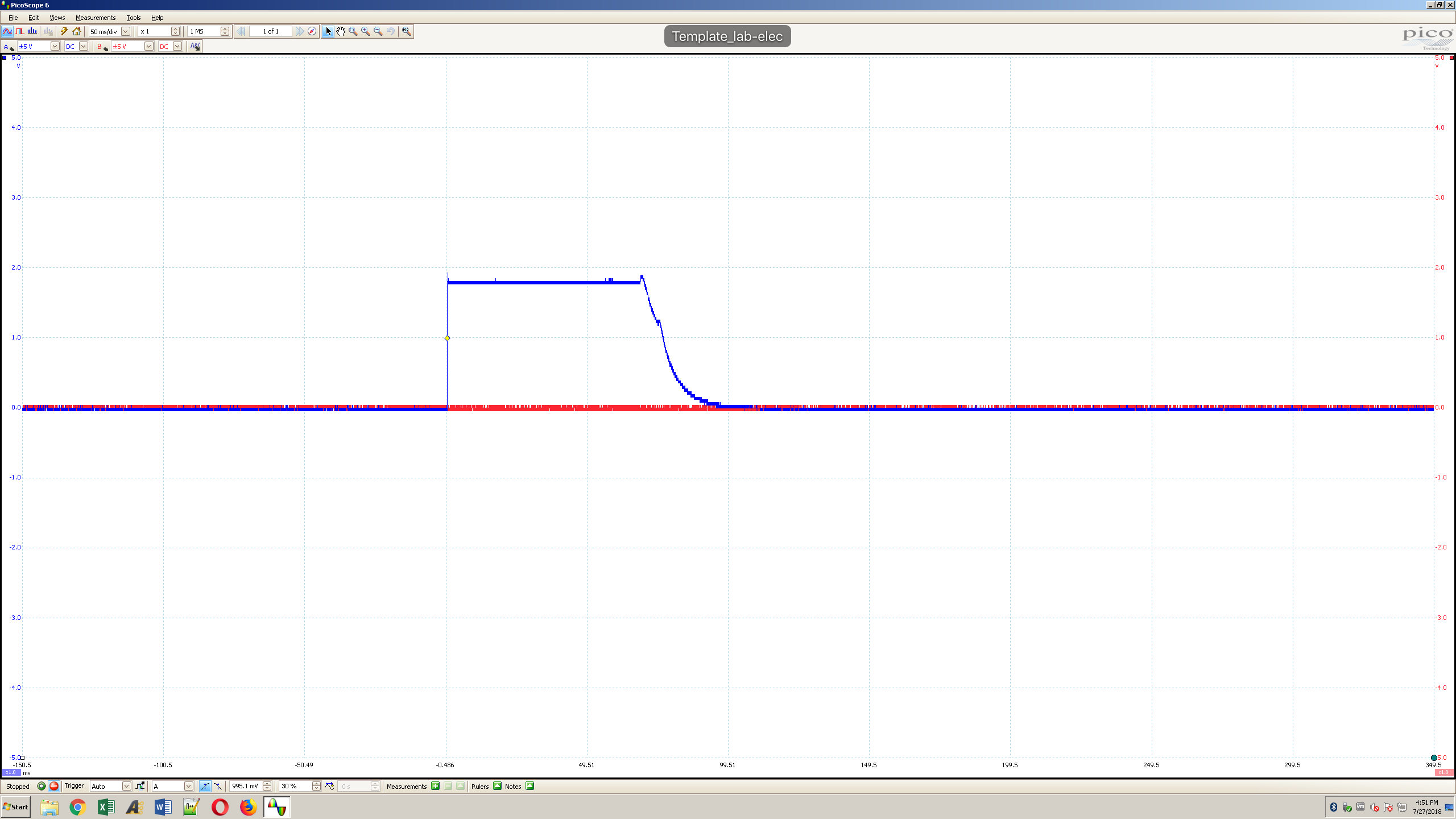
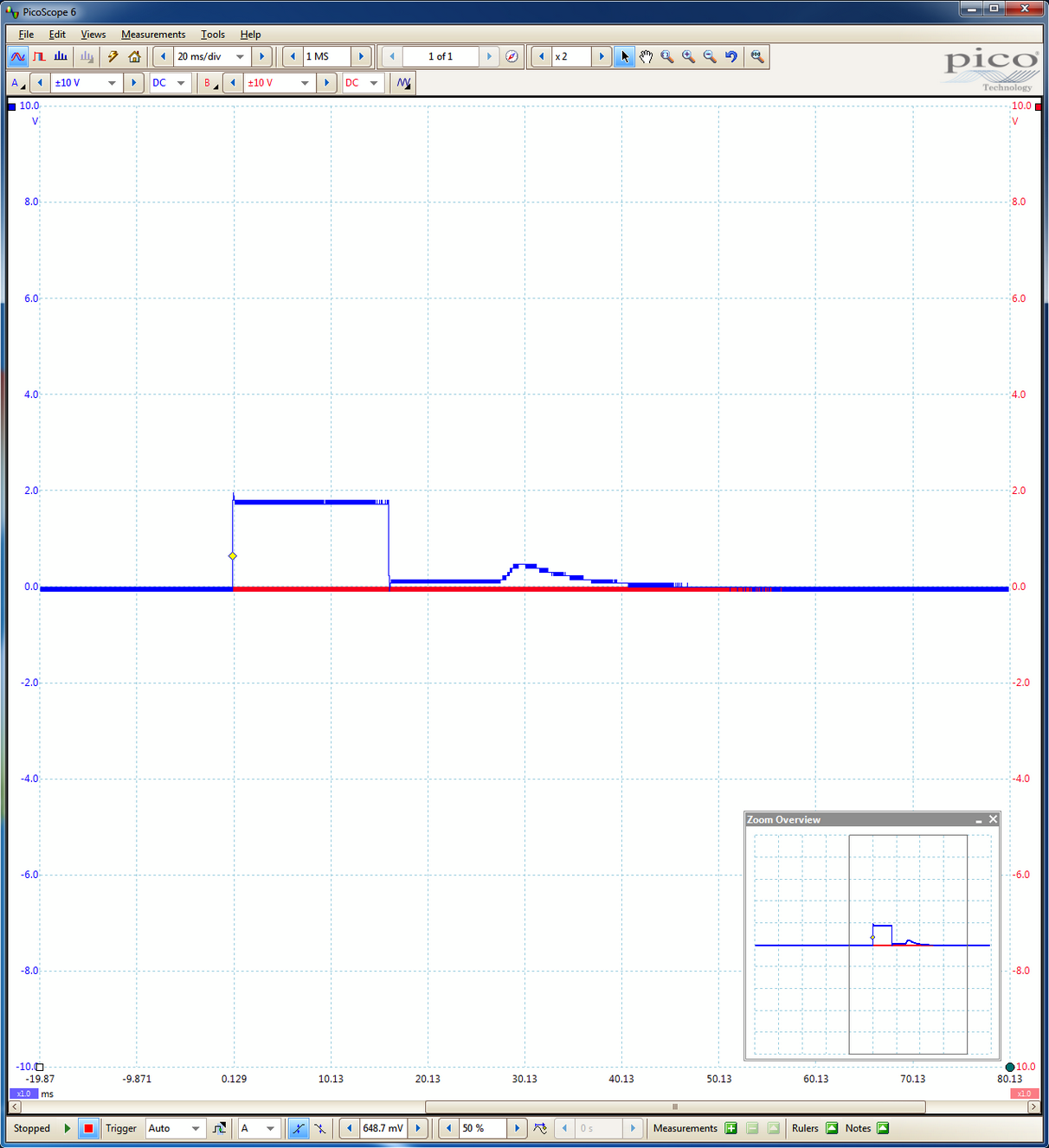
  • The wake up unsuccessful start (red line: NC, blue line: WAKE_UP) .

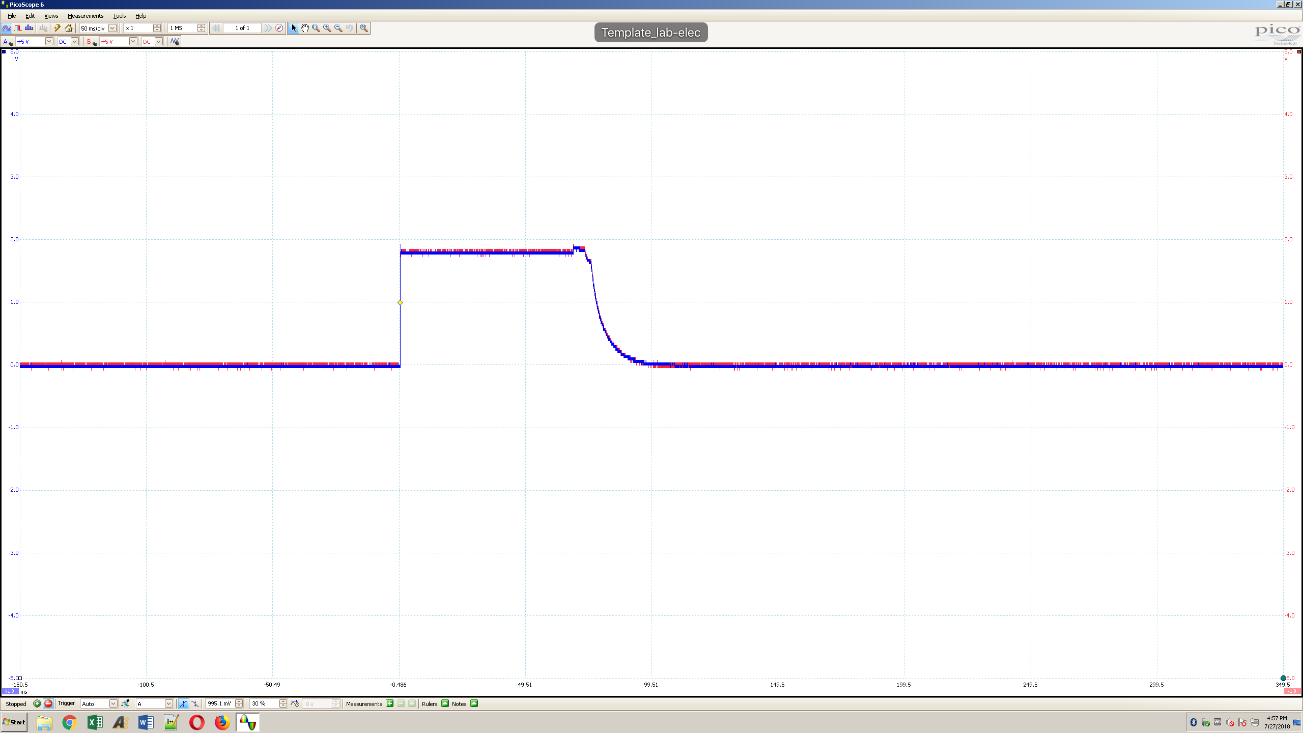
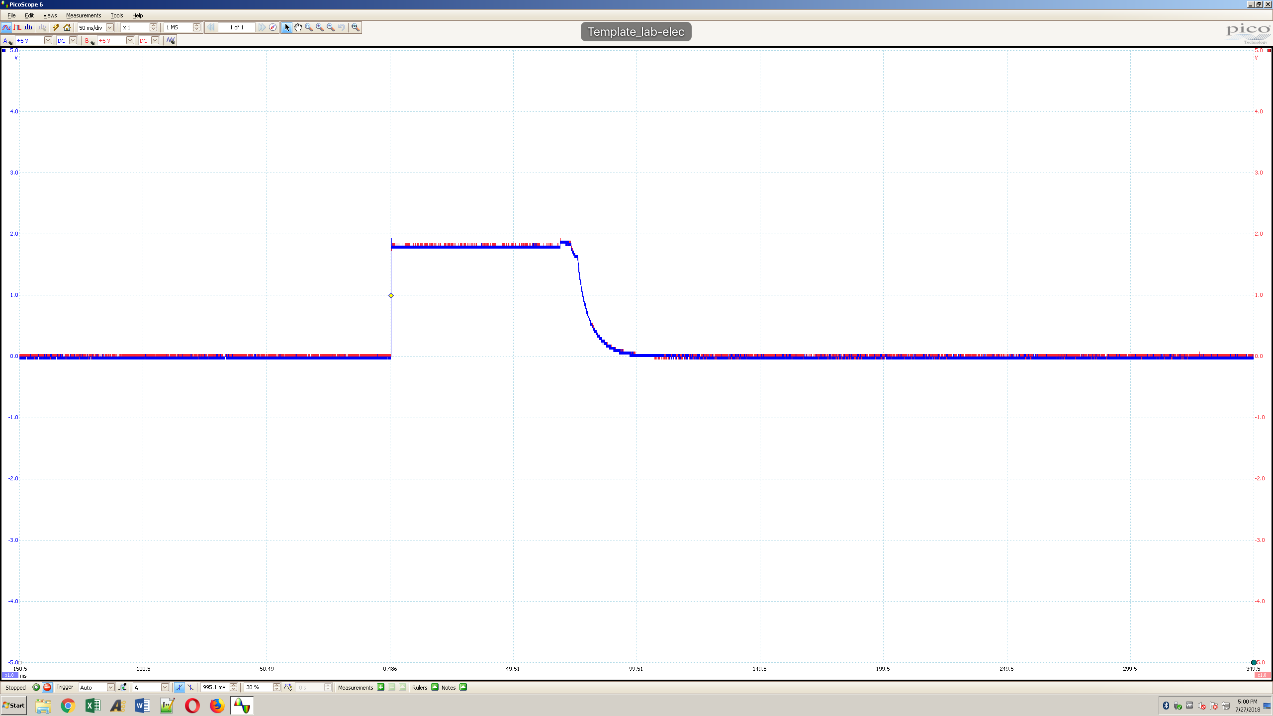
  • LDO1, PWR_EN and WAKEUP are enabled at the same time, but according to the Power-Up Sequence for TPS65217C, these lines shouldn't be enabled at the same time.


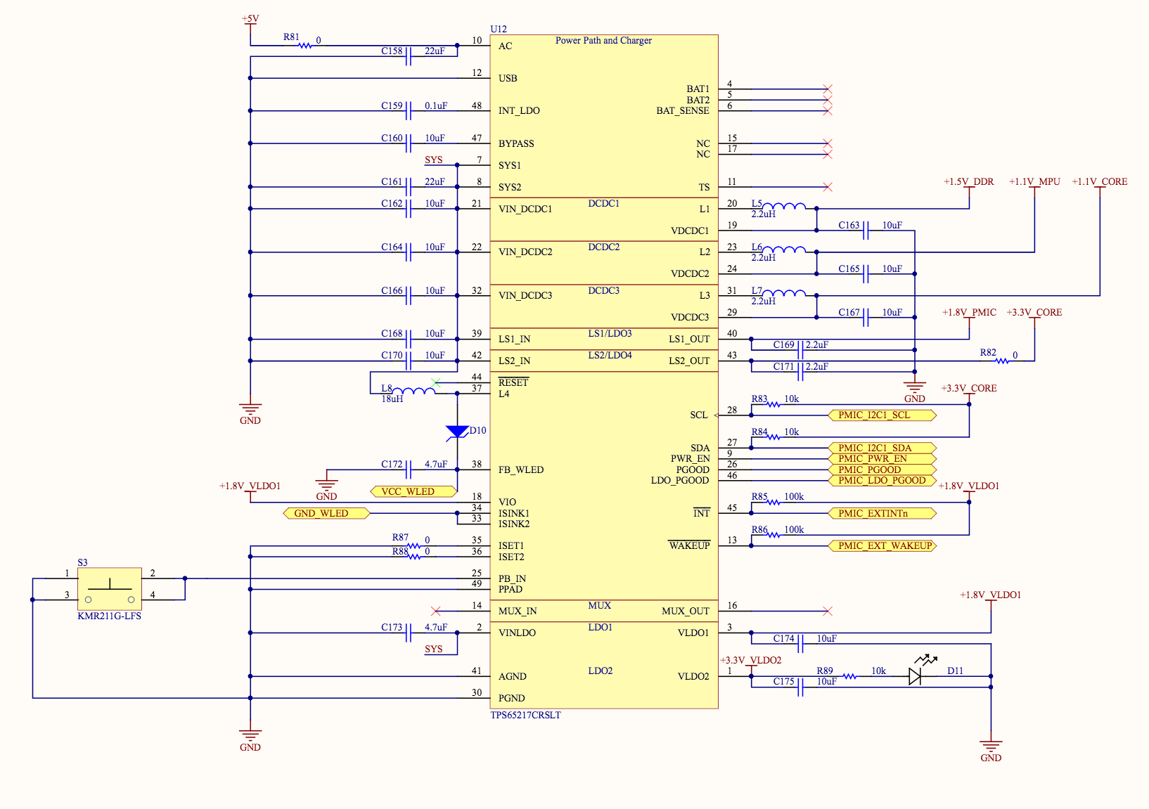
My PMIC Schematic is:


Do you have any suggestion to fix my issue?

  • RSET1 and RSET2 are not the correct value in your schematic. ISET1, ISET2 cannot be shorted directly to GND. Refer to the datasheet for optional RSET1/2 values.

    Based on the timing you have shared, it looks like one of the rails powers on and fails to get to regulation. This causes a fault and the PMIC shuts down.

    You will need to measure the output rails of the PMIC in the order they are sequenced and determine which one fails to reach the desired output voltage: DCDC1, DCDC2, DCDC3, LDO2, LDO3, or LDO4. And then you will need to determine why it is failing: it could be a short to GND or a load that is pulling too much current, for example.

    If the WLED driver is enabled during your sequence, then this is likely the problem because the equation for ILED = 1048*1.24V/RSET. If RSET is 0-Ohms, ILED approaches infinite current and the PMIC will see a fault every time the WLED driver is enabled.
  • You was right, fixe resistances of RSET1 and RSET2 has solved my problem for my second PMIC!
    For my first PMIC, I think there is broken.
    My test has include to:
    - several power up and off the PMIC.
    - listen PMIC pins with oscilloscope.

    Is it possible the repetition of this manipulations has broken my first PMIC?
  • It is possible that your testing damaged the PMIC.
    The feedback into the WLED driver is current value. Since the current is never high enough, the boost converter keeps increasing the voltage of the WLED driver.
    VOVP of boost is 38V in TPS65217 datasheet, but max VOUT is 32V. The ABS_MAX of L4 and FB_WLED pins is 44V, but it is possible the boost overshoots the abs max in a few cycles, before the OVP protection takes effect. If you test this enough times, it could cause damage.

    Do you have additional samples you can use to replace the TPS65217 IC with a new sample? It is not too difficult to re-solder This will answer your question :-)