This thread has been locked.

If you have a related question, please click the "Ask a related question" button in the top right corner. The newly created question will be automatically linked to this question.

LM5066I: LM5066I not turning off properly

Part Number: LM5066I
Other Parts Discussed in Thread: LM5066, LM5069, TPS2660, TLV333

Hello everyone,

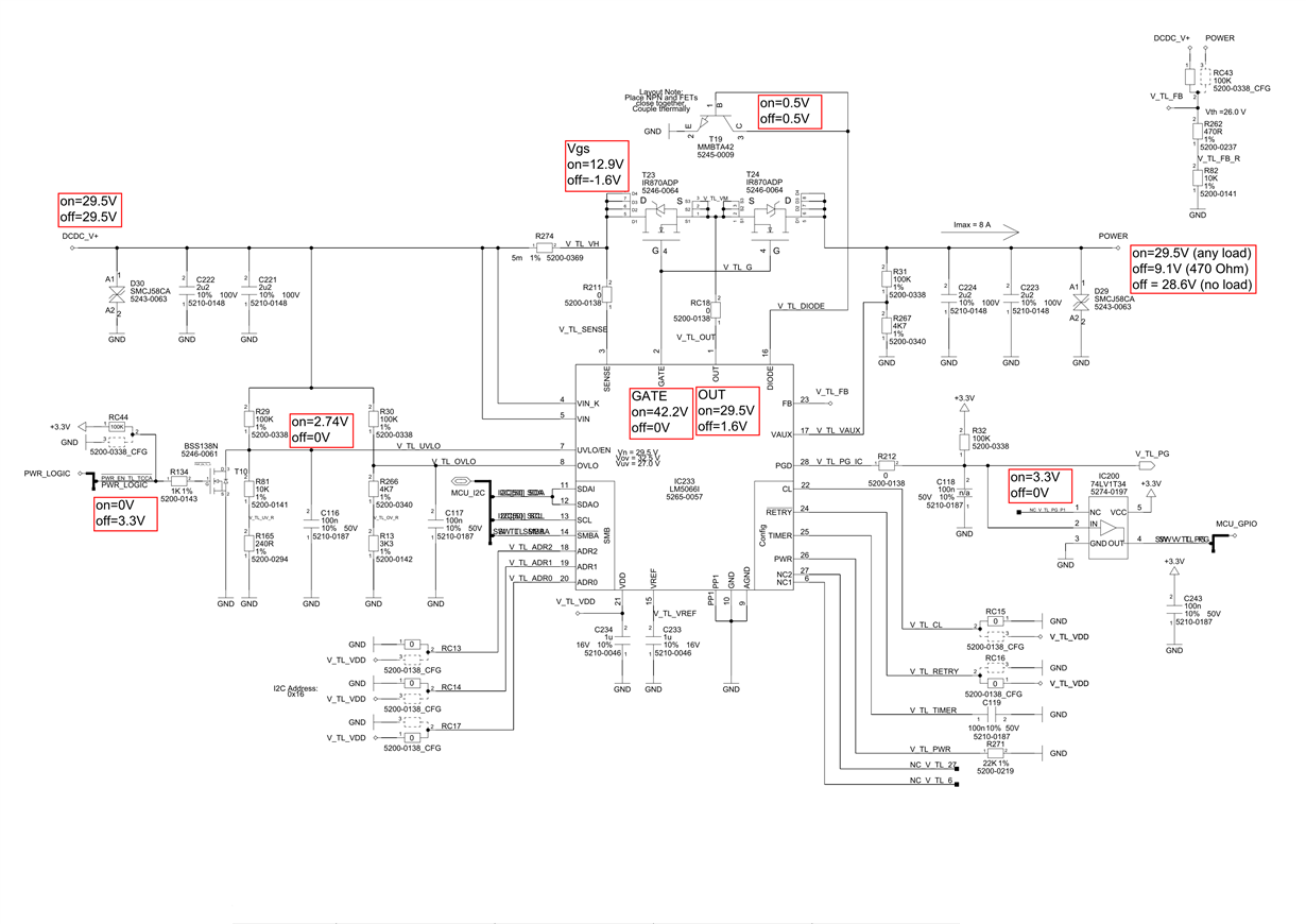
I'm currently working on the LM5066i, especially trying to switch a load with it. I'm using the attatched circuit with two SIR870ADP as switching FETs like in Application note SNVA673 to prevent reverse current.

Turning on seems to work fine. The input is 29.5V and can be measured on the outside as well, even when a load is connected. Unfortunately the output voltage labeled POWER on the right acts strange when turning off the device via the UVLO/EN Pin. Without any load connected, the voltage stays at ~28.6V. When connecting a 470 Ohm resistor, the voltage drops to ~9.1V. The output voltage is also ~28.6V when the LM5066 is turned off, the resistor is connected and then again disconnected. So it cannot be any charged capacitance on the output. The output signal POWER is connected to a pin on a connector and nothing else.

My first thoughts about why the circuit is not working are the two MOSFETs, like in SNVA673. In this application note, the LM5069 is used which differs from my used LM5066. But as the function seems to be similar, I do not know it this is really the reason.

  • Hi Christian Waechter,

    Can you please share test waveform of Vin, Vout, UVLO/EN Pin, GATE voltage

    Best Regards,
    Rakesh
  • Hi Rakesh,

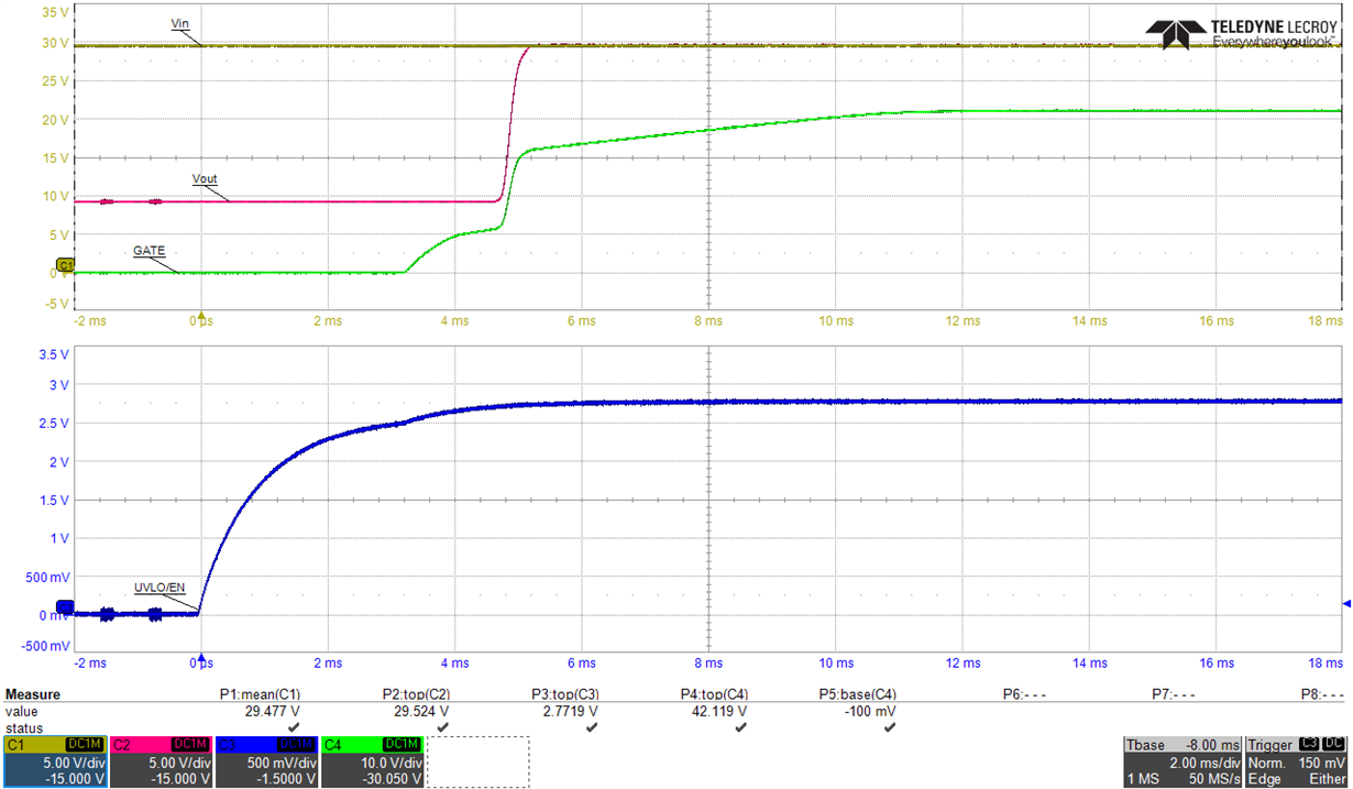
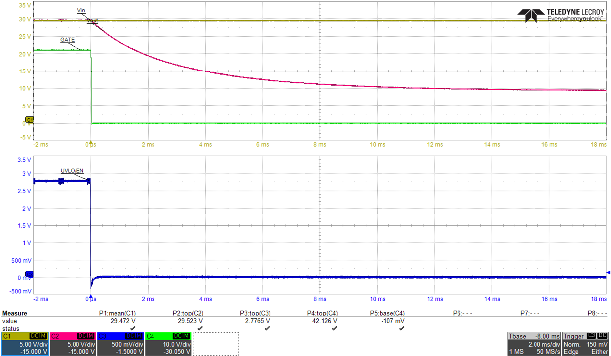
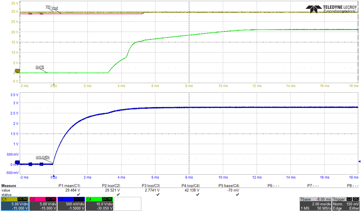
    I recorded some waveforms during startup and shutdown, triggered by the UVLO/EN-pin. Once with a 470 Ohm load, once without any load

    Startup with 470 Ohm load

    Shutdown with 470 Ohm load


    Startup without load


    Shutdown without load


  • Hi Christian Waechter,

    Vout =~Vin at no-load in disable mode concerns me. Is there any other path feeding the Vout and causing to drop when loaded with 470 Ohm load.

    Is RC43 mounted?

    Few things to try: Please look at input current with 470 Ohm load to check from where the Vout is getting powered; Next replace T23, T24 MOSFETS (one at a time) and verify.

    Best Regards,

    Rakesh

  • Hi Rakesh, thank you for your answer,

    I cannot see or measure any other path from Input (DCDC_V+) to Output (POWER). I also do not think that this is a random short circuit, because this problem is on multiple of these boards each with 3 LM5066i.

    RC43 is assambled so that DCDC_V+ is connected to V_TL_FB. The third pad to POWER is not connected on RC43.

    One thing about the DCDC_V+-voltage. It is generated by a DCDC-converter, that itself is turned on and off. This means, that the LM5066i is not always supplied via the Vin pin (pin 5). Also it is guaranteed by a hardware logic, that  the UVLO/EN Pin of the LM5066i is never on a high level, when the supplying DCDC-converter is turned off or starting up. The supply of the other components (+3.3V, +12V, ...) is always on.

    I recorded the currents through with and without a 470 Ohm resistor in the on- and off-state of the LM5066. It looks like the output is only supplied by the DCDC_V+ input as intended.

    LM5066 off LM5066 on
    input Current, no load 23.1 mA 23.5 mA
    input Current, 470 Ohm load 42.02 mA 83.91 mA
    output Current, no load 0 mA 0 mA
    output Current, 470 Ohm load 19.17 mA 60.6 mA

    I'm going to try changing the FETs and will report as soon as I have anything.

    Best regards,
    Christian

  • Hello again,

    I think i found the reason for the output voltage, even with disabled power switch. As I wrote in the first post, I'm using a circuit for reverse current protection from Application note SNVA673. There is a resistor R4 which originaly is 10k and is connected to Vin via the Diode D1. The resistor was changed to 1k in my circuit, which than will cause a voltage drop of ~2/3 when a 470 Ohm resistor is connected externally (remaining ~1/3 voltage drop).

    Is there any idea on how to avoid this behaviour when using this kind of reverse current protection? Changing the resistors is required as they adjust the trigger voltage/current.

  • Hi Christian Waechter,

    How much is your load current? Can you go for integrated solution TPS2660 eFuse to overcome this challenge. Let me know.

    Best Regards,
    Rakesh
  • Hi Rakesh,

    I'm expecting continuous 10 A at 48 V and reverse voltage of 60 V. I would like to avoid a integrated solution and use the already designed discrete circuit shown with the LM5069.

    What do you think, might a single diode in series with the resistor R4 do the trick? Anode connected to VOUT, Cathode to R4.

    Best regards,

    Christian

  • Hi Christian,

    We can go for an low offset Opamp or tuning R3 value while R4 remain constant.
    Placing diode in series with R4 will not allow to sense the Vout

    Best Regards,
    Rakesh
  • Hi Christian,

    Did you able to find something? else post a query on Opamp forum for the part recommendation.

    Best Regards,
    Rakesh
  • Hi Rakesh,

    I was not yet able to try serializing a diode with R4.

    The problem is not the Opamp. I'm using a TLV333 with only 15 uV Offset.

    The problem is that the input voltage can be measured on the output, even when the LM5066 is turned off. This is because there is a conducting path from VIN through D1 and R4 to VOUT. Increasing R4 would not solve the problem completely as this would still require a load on the output.

    The question is how to improve this circuit for the reverse current protection. Has noone else ever build this and faced the same problem?

  • Hi Christian,

    It looks, it is not a suitable solution where complete input to output isolation is needed. For reverse current protection at your current level of 10A, an ideal diode controller would be more suitable and again for hot-swap function LM5066I is still needed in series.


    Best Regards,
    Rakesh