This thread has been locked.

If you have a related question, please click the "Ask a related question" button in the top right corner. The newly created question will be automatically linked to this question.

BQ24040: Fast charge current way less than expected (~100mA)

Part Number: BQ24040

Hi!

I've been testing the designed I've made, based on BQ24040 (and some other IC's) and I've stumbled across a problem that I don't seem to find the solution to: the fast charge current is 92mA, although it is set via an external resistor to 800mA.
Power comes for a strong R&S HMC0842 PS set a 5V / 1.5A and is supplied to a DTP603450 Li-Ion battery.

What I've done:
- I've tested the voltage drop across the 10k TS resistor and it is 0.5V, so 50uA is going trough TS as expected
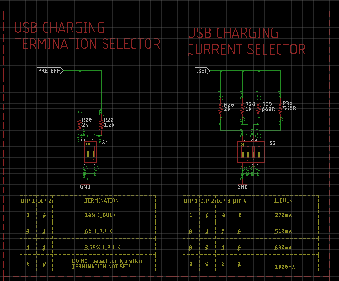
- I've tried multiple ISET resistor values with the same result (fast charge current is not rising more than 92mA)
- I've tried multiple PRETERM resistor values with the same result (fast charge current is not rising more than 92mA)
- I've double and triple checked the datasheet and the schematic
- I've made sure pre-charge is not going on; the battery voltage it's at +3.6V so fast charge should be fully kicked in


Some other things:
- D3 LED (connected to CHG) is also not lighting up
- D1 LED (connected to PG) is lit up permanently while power is connected (when VIN < 4.2V, D1 goes off)

Any idea on where the problem might resign?


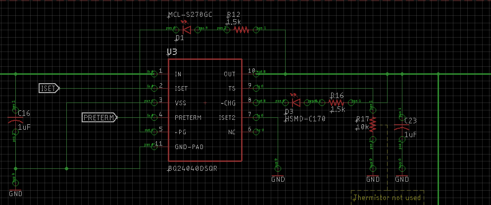
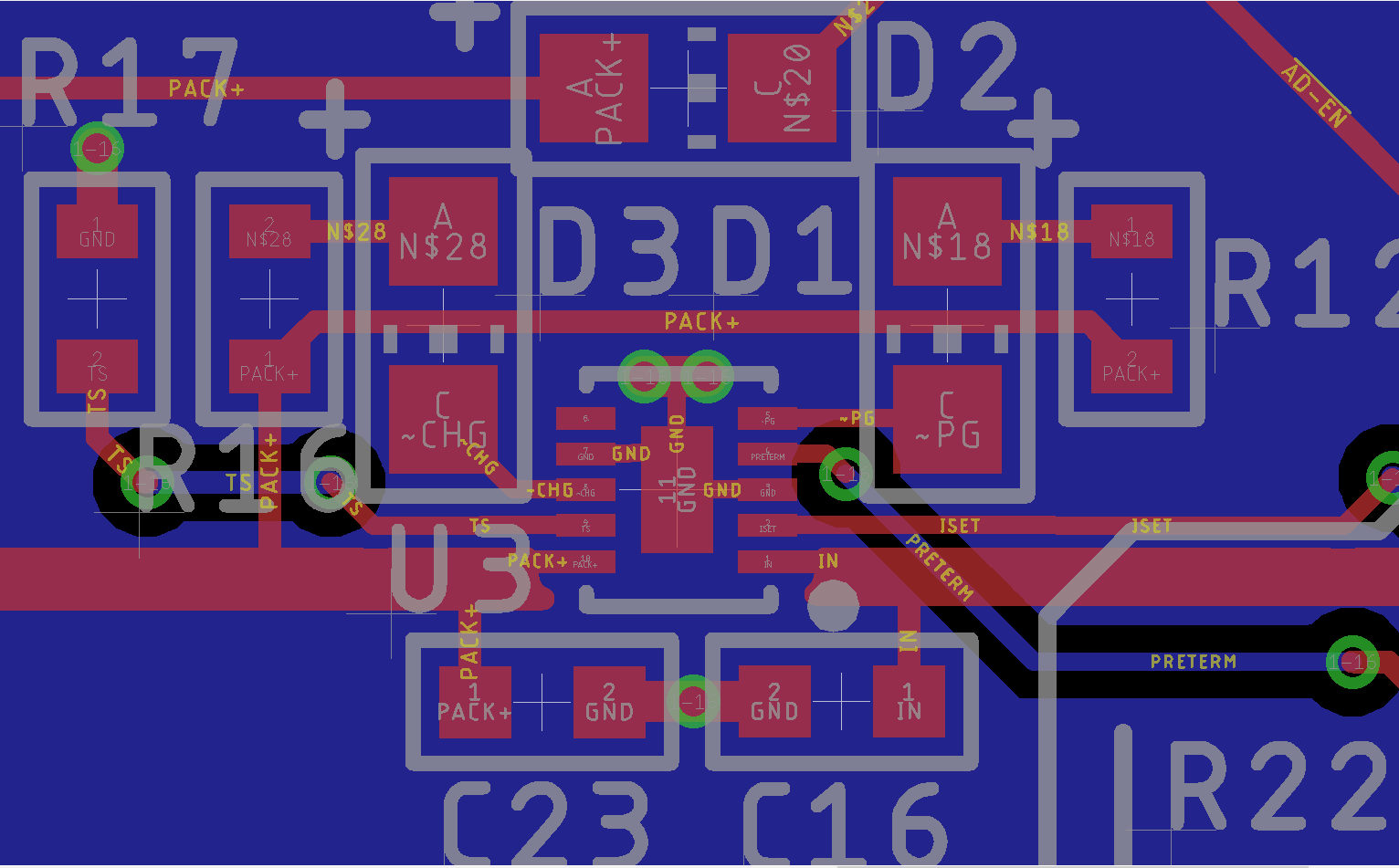
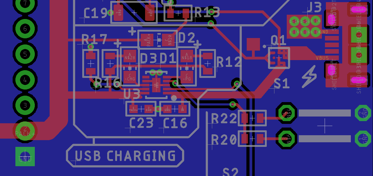
The schematic is as following:

  • Hello
    Fast charge current is 92mA but should be 800mA.
    Some things to check:
    1.) If ISET2 pin is floating it will limit input current to about 100mA, double check that the pin is grounded, no issue with solder joint.
    2.) If battery voltage is below 2.5V at the OUT pin unit will be in precharge, double check voltage at OUT.
    3.) If input to output voltage drop is too low it will reduce output current. For a battery at 3.6V and 800mA the input Voltage should be over 4.6V.
    4.) Double check ground connections on the device, input gnd to Pin 3 and battery gnd to pin 3.
  • Bill Johns said:
    Hello
    Fast charge current is 92mA but should be 800mA.
    Some things to check:
    1.) If ISET2 pin is floating it will limit input current to about 100mA, double check that the pin is grounded, no issue with solder joint.
    2.) If battery voltage is below 2.5V at the OUT pin unit will be in precharge, double check voltage at OUT.
    3.) If input to output voltage drop is too low it will reduce output current. For a battery at 3.6V and 800mA the input Voltage should be over 4.6V.
    4.) Double check ground connections on the device, input gnd to Pin 3 and battery gnd to pin 3.


    First, thanks for the reply!

    1) ISET2 is properly grounded, I've checked it before posting and again a few moments ago.
    2) Battery voltage is at +3.68V (measured right at the OUT pin of BQ24040)
    3) Input to output voltage drop is +1.25V which is way more than enough to trigger fast charge
    4) I've double checked the GND connections as well as all connections to the IC. The IC is properly soldered via reflow soldering.

    To get a better understanding here is the layout on the PCB:

    And here's a wider perspective of the PCB layout:

  • Check the temp or thermal rise of the device.
    When the die temp reaches 125C it will reduce output current to prevent temp from increasing beyond this point. Thermal impedance from the die to case will lower this number to the 80C range on the case.
    In the layout it looks like the ground plane is on the lower layer and do not see vias connection thermal pad to it.
  • The temp is OK.
    Unfortunately I don't have a thermal camera, but I can assure you it's not the case. The ambient air temperature of the room I'm testing in it's 20°C. When touching the IC it doesn't even feel warm to the touch. Much more, the charging current stays at 92mA right from a cold start, further ensuring me thermal protection is not the culprit.
  • How many boards are showing this behavior?
  • For the moment I've built only one prototype, so I only got to test 1 BQ24040.

    Is there a problem if during the first boot none of the ISET and PRETERM resistors were connected? What I mean is that during the first boot, when I've tested the board, ISET and PRETERM were floating. After that I've remember about selecting one of the resistors trough the dip switches.

  • Are you OK taking this conversion off line, private message feature of forum.
    I will send you a request.
  • Sure. We can discuss the matter in PM.
  • After changing the IC with a second one, the circuit performed as expected. So, the problem was with the IC itself being faulty.