This thread has been locked.

If you have a related question, please click the "Ask a related question" button in the top right corner. The newly created question will be automatically linked to this question.

BQ76940EVM: Understand the Polarization of the MOSFET - Custom

Part Number: BQ76940EVM
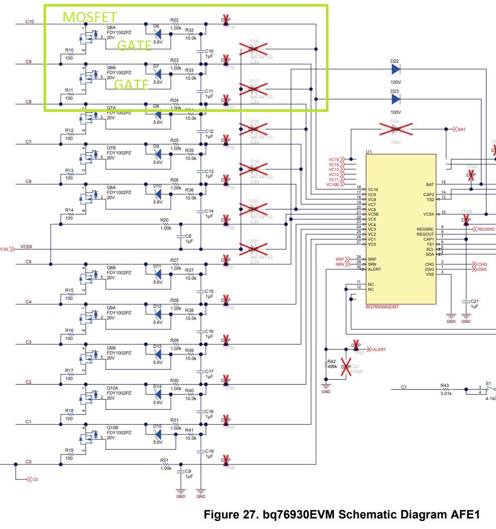
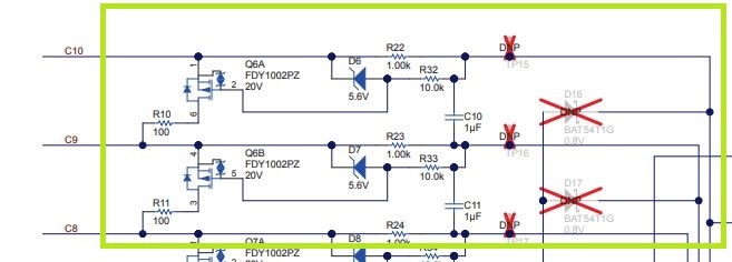
Other Parts Discussed in Thread: BQ76940

Nowadays I´m working in version custom bq76940, but I dont´understand about:

1) Mosfet Q6A and Q6B, and your voltage in gate door.

2) Diode D6

3) Resistor R22, R32

4) capacitor C10

www.ti.com/.../slvu925b.pdf


The components are on figure below.


Best Regards

  • Hi Andre,
    Only 1 of the 2 FETs operates a the same time. The basic current flow is shown in www.ti.com/.../slua749 figure 5.
    R22, R23 and C10 are the input filter for the cell (R23 is shared with the lower cell).
    During balance current flow VC10 and VC9 pull together. A representative picture is figure 5 in www.ti.com/.../slua775 . This creates a voltage across R22 (and R23 if using N-channel).
    R32 brings the R22 voltage to the Q6A gate. Q6A turns on and current flows in R10.
    D6 protects the gate and R32 limits the current in D6 as explained in slua749 figure 7.

    N-channel balancing may have benefits as noted in slua749.