This thread has been locked.

If you have a related question, please click the "Ask a related question" button in the top right corner. The newly created question will be automatically linked to this question.

OCD/SCD threshold value problem

Other Parts Discussed in Thread: BQ76930

I use TI 76930 AFE.
The Rsense is 1m Ohm.
I set the AFE OCD and SCD threshold as 89mV and 111mV.


When the current is 78A or so, AFE OCD bit is set and D_FET off.
When the current is 89A or so, AFE SCD bit is set and D_FET off.

How come AFE OCD/SCD works while current does not exceed the OCD/SCD threshold?

Thanks

  • Hi Matt,
    Check the PROTECT3 register 0x08. Be sure the reserved bits 3:0 are being left as 0. Some earlier revisions of the data sheet showed the reset value as 0x08 causing some programmers to set bit 3. If that happens the current thresholds are reduced similar to what you describe. Please use the latest data sheet.
  • Hello,
    For register PROTECT3 (0x08)
    I set the UV_D1, UV_D0, OV_D1, OV_D0 to 0 and I read PROTECT3 (0x08) register, the register bits are all 0, not 0x08.
    So, the problem may not caused by this
    any suggestion?

    Thanks
  • Hi Matt,
    If the register is set correctly the problem must be elsewhere.
    Look at the voltage across the sense resistor, the voltage across the resistor solder, and the voltage between the resistor and where the trace to the sense filter branches off the high current path. Trace and solder resistance can be significant. Also look at the voltage at the sense pins on the IC.
    The problem was not with the register setting, if the problem is not in the board/component resistance, the part must be damaged since the tolerance is only 10% and you are seeing more like 20%.
  • Dear 

    Sorry i can't catch you, can you describe more clear or do you have any document which describe this ?

  • Hi Frank,

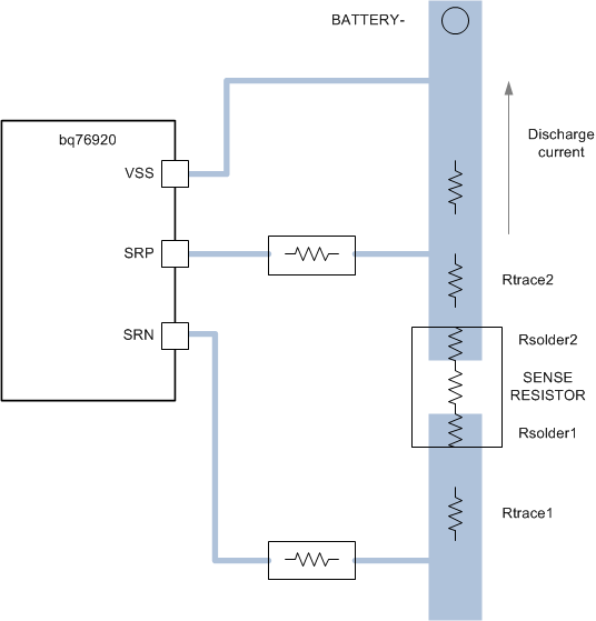
    The connection to the sense resistor should be made with a "Kelvin" connection as close to the sense resistor as possible.  This avoids contribution of the voltage caused by current through the parasitic resistances into the sense voltage seen by the bq76930.  In this picture the bq76930 will sense the voltage Idischarge x (Rsense + Rsolder1 + Rsolder2 + Rtrace1 + Rtrace2).

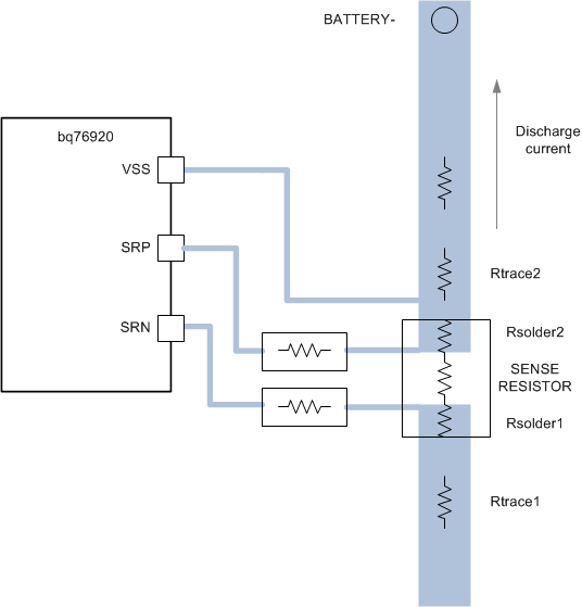
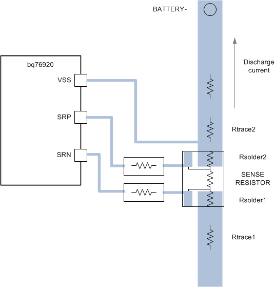
    Routing the sense traces to the pads will eliminate the trace resistance contribution.  In this improved connection the bq76930 will sense the voltage Idischarge x (Rsense + Rsolder1 + Rsolder2).  The resistor still must solder to the board.

    There are 4 terminal sense resistors made which avoid measuring the voltage across the solder resistance. These are less common.  The high current still causes a voltage drop in the high current path, but the sense connections are in the resistor package and the separate terminals are low current and do not experience a voltage drop.

    Inspect your layout and measure on your system to see if you can find the extra voltage.

  • Dear WM5295

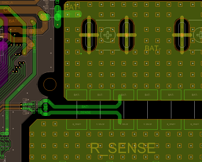
    Thanks for your explaining, after discussing with our EE and layout team, we did use "kelvin" connection in our layout 

    you can refer to the following diagram.

    do you have other ideas about this issue 

    thanks


  • Dear WM5295
    Is there any way to eliminate Rsolder1 and Rsolder2 effect ?

    thanks
  • Hi Frank,
    It seems they did a nice job with the layout. I don't know the effect of many parallel resistors, I don't know that we have used more than 3. The sense connection picks up the voltage of the bus at the point of connection.
    My understanding of the solder resistance is it should be small relative to the component value so that it is a don't care. The multiple parallel resistors should help with this. The 4 terminal resistor would also help with this, but would not work for parallel resistors. On a larger scale, there are mechanical shunts where the sense leads are connected to a monolythic part of the sensing material such as wires on a bus bar. That is a large version of the 4 terminal resistor.
    Your board assembly people may know if there is a different solder material or adjustments to the process or volume to give a lower or more consistent solder resistance.
  • Hi WM5295,
    The SCD register setting code as below:
    Does this SCD register setting correct for AFE SCD 111A threshold?


    bms.para.scd_delay = 0; //#define SCD_DELAY_70us 0x0
    bms.para.scd_thresh = 3; //#define SCD_THRESH_111mV_56mV 3
    bms.para.rsns = 1;

    registers.Protect1.Protect1Bit.SCD_DELAY = bms.para.scd_delay;
    registers.Protect1.Protect1Bit.SCD_THRESH = bms.para.scd_thresh;
    registers.Protect1.Protect1Bit.RSNS = bms.para.rsns;

    HAL_I2C_Mem_Write_TI_CRC8(&hi2c, I2C_ADDR_WRITE, PROTECT1, 1, &registers.Protect1.Protect1Byte, 0x1, I2C_TIMEOUT)

    Thanks
  • Hi Matt,
    Depending on your definition of the Protect1Bit positions I think it is right. Be sure the assembled Protect1Byte value ends up 0x83 for your desired setting and that the value ends up in register 0x06 of the bq76930