This thread has been locked.

If you have a related question, please click the "Ask a related question" button in the top right corner. The newly created question will be automatically linked to this question.

TPS55330: Vin regulation with the internal loop

Part Number: TPS55330
Other Parts Discussed in Thread: BQ25703A

Hello,

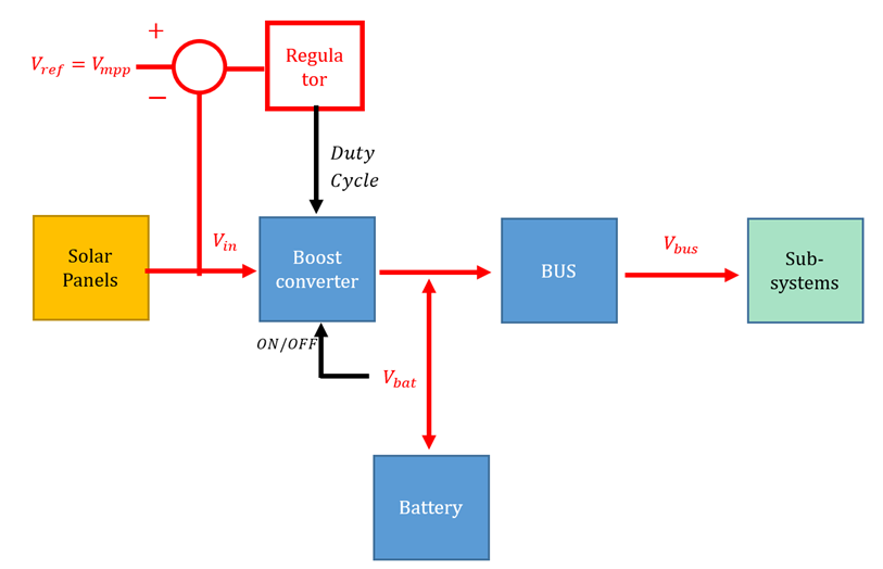
I want to use a Boost converter to charge a battery (8.2 V when fully charged) from a solar panel input. Knowing the MPP of the solar panel (7V, 4A), I want to regulate the input voltage Vin by controlling the duty cycle of the converter. In my Simulink model, my error amplifier between (Vin-Vref=7 V) directly feeds a PWM generator to drive the Mosfet.

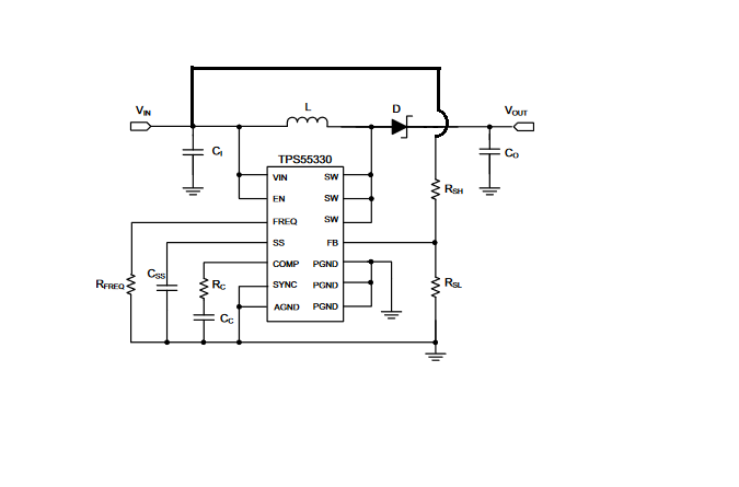
Usually, the FB pin of TPS55330 and others TI boost converter is used to regulate the output voltage. Nevertheless, would it be possible to connect the FB pin at the center of an input bridge divider in order to have FB voltage at reference voltage=1.229V when Vin=7V ?

I am wondering if this regulation would be compliant with the inner comparison between the output error amplifier and the Mosfet current signal ? 

Thank you in advance for your help,

Corentin

  • Hi Corentin,

    Thanks for choosing the TI part.

    Could you please draw a draft block diagram of what you want to realize? So that you can get our answer quickly.

  • Hi Helen,

    Thanks a lot for your fast answer.

    I am wondering if its possible to use the intern loop control of TPS55330 to regulate the input voltage of the Boost connected to solar panels.

    Rsh and Rsl bridge divider would be calculated to have FB voltage at reference=1.229 V when Vin is at the maximum power point (7V, 4A) and then we would have the output of the intern error amplifier=0. The circuit I want to use is below:

    Is it possible to do that?

    Thank you in advance for your help,

    Corentin

  • Hi Corentin,

    We never do in this way, this kind of connection may leads to stability issue.

    Could you please tell me why you want to connect in this way, to make Vo higher when Vin is lower or something else? ..... These information may help us to find out a better solution.

  • Hi Helen,

    Thank you for your advice. The block diagram below resumes what I want to do:

    I want to regulate Vin of the boost in order to charge the battery with the maximum input power.

    The Li-Ion battery voltage is 8.2 V when fully charged and sets the output voltage of the Boost.

    The solar panels voltage reaches 7V at MPP.

    I know some components like the charger BQ25703A can handle that but I am looking for a simpler component.

    I have modeled the connection of:

    solar panels input -> the boost converter -> Li-Ion battery

    and the transfer Vin/D (with D the Boost duty cycle) is stable in closed loop. So I want to regulate Vin at MPP when the battery needs to be charged.

    Can I use an integrated component which includes: the command (error amplifier +PWM generator) and the Boost converter ? (like TPS55330 but for input regulation)

    or should I use another component to make the PWM independently and control a Boost with that PWM?

    Hoping that my objectives are clear,

    Thank you again for your help,

    Corentin

  • Sorry my file wasn't attached in my last answer. This is what I want to do:

  • Hi Corentin,

    For the TPS55330 boost converter, Vo=Vin/(1-D) , so when Vin drops, its duty D will automatically get bigger.