Hai,
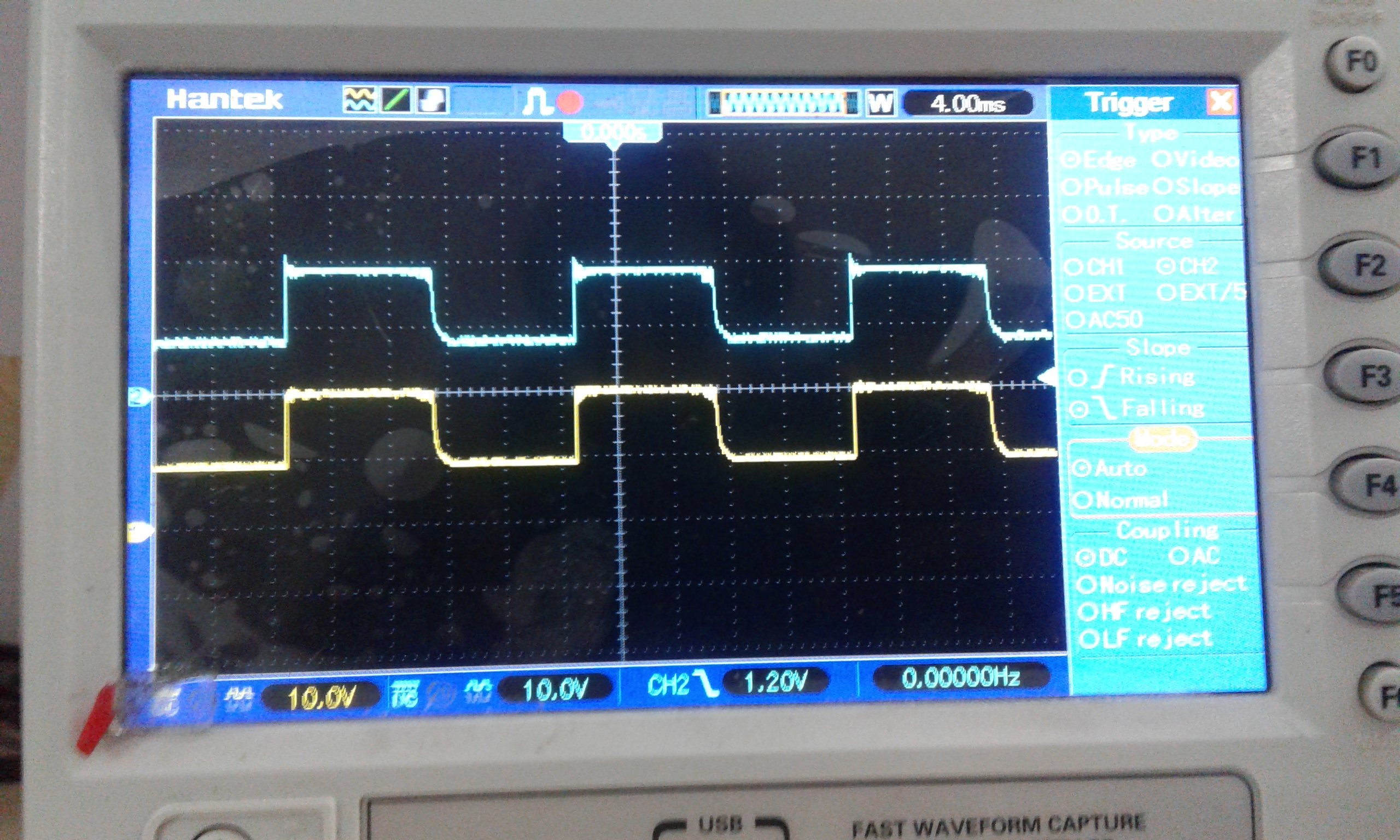
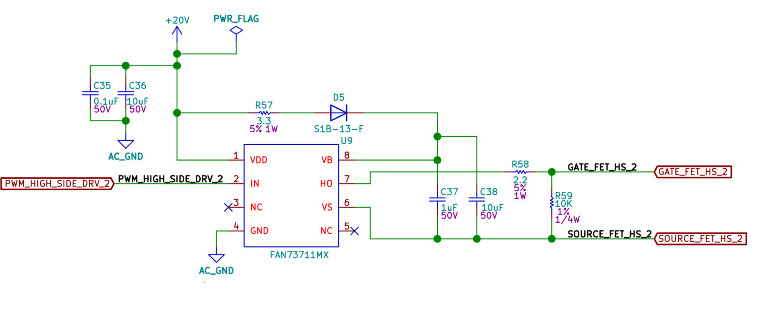
i am designing an pv based inverter.I have implemented h-bridge in my design.I have attached My High side driver schematics with this.As a part of testing i just drove a half cycle with two mosfets,one from high side and other from low side so that the path completes from vdd to ground.I happen to probe the VB and VS pins of the gate driver IC.I found it normally working until a particular Vds of 120v.When the VDS increased from 120V , the voltage on VS pin with zero reference ,level shifts above zero proportional to the increase in voltage.I mean to say that if the VDS is 120v the VS pin rises from a zero level to a particular voltage.But when VDS is increased from 120v....if the VDS is 150v, then the pulse level on vs shifts above zero level with a dc value of 30v.We found proportional increase in the level shift from zero level when we increase from 120v.I have attached rough sketch of the H_bridge with this.what could be the possible reason for the DC value or the level shift from the reference level in the VS pin in this design?Why isn't it not level shifting for VDS values below 120V?Please note that i am using max 200v variable power supply across the H-bridge.Is it due to my driver or is it due to the Mosfet i am using in my design?