This thread has been locked.

If you have a related question, please click the "Ask a related question" button in the top right corner. The newly created question will be automatically linked to this question.

WEBENCH® Tools/TPS61085: Meaning of derating

Part Number: TPS61085

Tool/software: WEBENCH® Design Tools

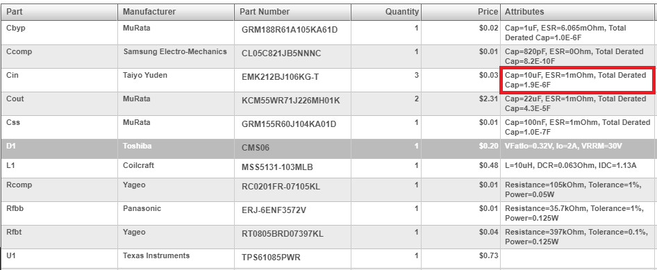
What does exactly mean that line highligted below?

I could not find derating info of this Taiyo Yuden P/N so I tried Kemet and Murata and neither derates 80% (as I first understood the info in that cell. FWIW, for a similar size, voltage and X5R item, Kemet K-Sim says capacitance reduces 10% and Murata SimSurfing says 50%.

  • Hi Sir,

    The person from the modeling team will answer your question, please wait in patient.

  • Hi Elder Costa17,

    We are estimating the total derated cap for ceramic capacitors only as a function of the applied DC bias voltage on that cap. If we have this derated cap data from the manufacturer for the cap, we use that value of the derated cap. In other cases, we use a linear derating of the form C_actual = Cnominal*(1-Vapplied/VDCrating) So, for example, for an applied voltage of 8V to a 16VDC rated cap, the nominal value would be cut down by half in the linear approximation. In this case, since we do not have data on the Taiyo Yuden cap EMK212BJ106KG-T we are using this linear derating equation. We use this derated value into account while doing the cap selection so we do not end up picking a capacitor that will not meet the capacitance requirements of the design. You can click on "Select Alternate Part" on that capacitor and pick another capacitor that has more effective/derated cap if you like.

    Please let us know if you have any more questions.

    Regards,

    Amod

  • Hello, Amod,

    First of all, thank you very much for your answer. It makes more sense to me now.

    FWIW, digging in Taiyo Yuden web pages, I found a tool that show the P/N parameters. For this P/N in particular the derating is 50% at 5V. The tool also raised some questions but I think I will open another thread after digging more into it.

    I have another question though. I think it is related to the OP so I will ask it here. The output capacitance suggested is 43uF as you can see in the BOM and it picked a very expensive part (probably based on the derating too). However I reduced the capacitance to 15uF (already derated) and the results look OK: ripple is higher, obviously, but still OK for my application and transient response is nearly identical and it looks stable.

    So the question is how the output capacitance is determined and how much can it be safely varied.

    Once more, thank you for your support.

    Elder.
  • Hi Elder,

    Thanks for the information on the Taiyo Yuden tool. Please let us know the details when you can.

    We use steady-state ripple and load transient voltage requirements for designing the output capacitor.  We have a recommended limit mentioned on the Alternate parts page for Cout. You might be able to get a working design with slightly lower values as well but like you said, you might end up compromising on the ripple or transient response and also stability in some cases. In general, it would be best to test out the design with updated Cout on the bench with a test board to ensure you are getting the response you expect.

    Regards,

    Amod

  • Hello, Amod.

    This is helpful, thank you very much.

    Elder.