This thread has been locked.

If you have a related question, please click the "Ask a related question" button in the top right corner. The newly created question will be automatically linked to this question.

Need Controller for Push Pull Inverter

Other Parts Discussed in Thread: UC3872

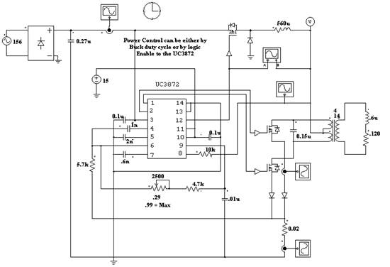
I am needing a controller for a variable frequency current source Push Pull Inverter that I want to develop.  it will run into a parallel tuned resonant load, around 10 to 60 kHz, 1-3 kW for now.  I was looking at the UC3872.  This has a Zero detect pin that I could monitor the output transformer center tap with to track the load frequency.  My power circuit is from single phase 120 and 240 V 60 Hz.  This is higher than what that chip is rated for.  Is there a way to voltage divider the signals down to what the chip needs, or does anyone know of a better way to do this?

  • You need to provide a lower power supply voltage for the IC   -- this is normally done across the industry  -- just enough current with voltage clamp to allow the IC to start operating then the IC itself could supply the defined lower voltage -- since you are not very informative it is difficult to suggest a basic circuitry  -- I have used this family with 400 Volts supply -- and the signals can be divided down to your operating range including clamps to limit and protect the IC.

    Send the info and I will reply.

    Nando


  • Nando,

    I am attaching an image - I hope.  This is my first time on this forum.  Supplying the chip with an external dc supply is not a problem.  Issues that I have a problem with is 1) How to get the signals that are too high for the chip down to chip level, 2) How to control the buck output (I would like it to be the power control and current limit, and 3) How to drive the gates of the power devices (Buck and the two push pull devices.  Do you know if there is a better chip or another way?


    Thanks - John

  • JOHN:

    You are not supplying enough information to know what you are wanting to do.

    The Buck converter uses a P mosfet that basically if the  supply voltage is greater than than the IC limits, an isolation driving circuit needs to be added.and If the supply is above the IC level is preferable to change the mosfet to a N type and invert the drive signal, in this case use something like the IR2575 mosfet driver that can be used to read the current and still drive the  inductor .

    Dirvers TC4412 for Mosfet type N or the TC44123 or TC4424 dual drivers for Mosfet  type N depending if non inverting or inverting are needed

    Current detection depends on the way you need to capture the signal and its levels -- like for the push-pull circuit a resistor , as show in your basic circuit, and the value of it for a range reading as defined by the UC3872 input capabilities same goes for the  IR2575 capabilities and its current detector resistor.

    There are many variables that you need to take in account to decide what type and level current readings that you need to cover -- that are beyond the purpose of this  messages since you are not giving any clear design parameters to take in consideration .

    The basic circuit like you have supplied is able to produce suppies better than  500 watts if the Mosfets and the drivers are properly selected.