This thread has been locked.

If you have a related question, please click the "Ask a related question" button in the top right corner. The newly created question will be automatically linked to this question.

TPS63070: Reducing ripple with low loads in power saving mode

Part Number: TPS63070

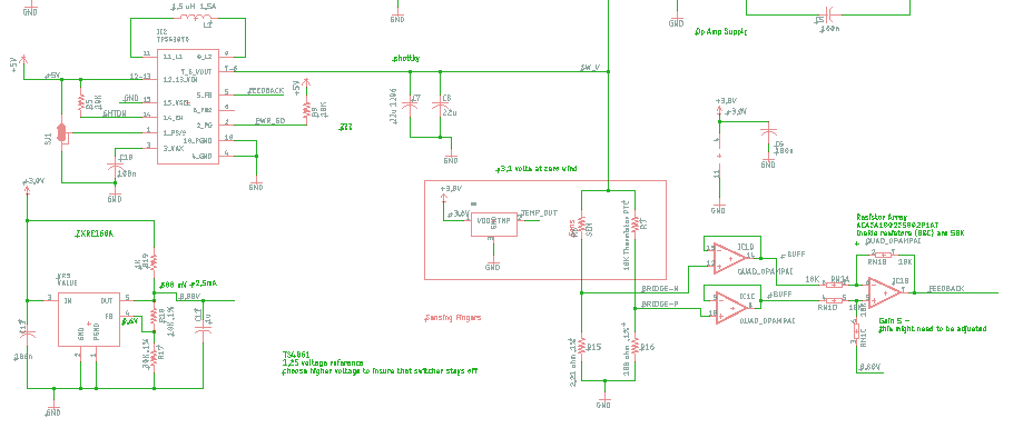
I'm using the TPS63070 with a Wheatstone bridge that provides feedback to the converter. I've got a working proto but the switching frequency is too low with too much ripple.
In the next proto I'll set the PS/SYNC low for a comparison to see how that works out, but I like the idea of power saving mode, I just want a frequency about 10 times as fast as it's working now.

Here are my approximate specs

Input V:  3.3, 5V maybe 12V

Output V: 3 - 9 V

Output Current 20 mA to 120 mA

Here are some scope traces, from what I can see from reading the datasheet  they look about as they should.
I would welcome some comments on them  however if you disagree. Is is possible that my op-amp isn't fast enough or my loop gain high enough.

I'm using a loop gain of about six at the op-amp now that goes to the feedback input.

Blue trace is the output, yellow trace is feedback. Triggering on feedback trace.
Output is a little over 3 volts.

At 2.6 V input.

At 5.0V input

I'm currently using 1.5 uH now and 44u output caps.

Here are some things I was gong to try.

Smaller inductor?
Smaller output caps?
Higher gain at op-amp
Faster op-amp

Thanks much for any suggestions you can provide.

Paul

  • Hello Paul,

    Thank you for the question. I will take a look at the schematic, and get back to you by the end of the day.

    Best regards,
    Milos
  • Hello Paul,

    This ripple seems to be too high, more than 2 Vpp, and looks more like some kind of oscillations due to instability of the circuit, and not due to switching/mode of the regulator (or L/Cout values). At loads below 600 mA, TPS63070 works in PFM mode with ripple below 50 mV, and with much higher ripple frequency for your range of output current (at 20 mA already above audio). Likely, the compensation is not right. For start I would try changing the loop gain. Please let me know if the tests you plan to do make any change. 

    If I am not mistaken this is a wind speed sensor and you need to heat an element? Please also take a look at SLVA251 application note, or TEC driver reference design PMP9759. It is better to provide the setpoint voltage and disturbance regulation through standard voltage divider feedback (placed as close as possible to the regulator), and slow voltage corrections through an external circuit (in your case the bridge and differential amplifier). In your circuit, the disturbances in the output voltage of the converter are seen as common mode voltage by your sensing circuit and are suppressed, which might be the reason why the voltage oscillates. 

    Best regards,
    Milos 

  • Thanks for the help, I'll report back. I had considered a scheme similar to SLVA251 app note, but wondered if I would have a wide enough range of control with the scheme. I guess I need to look at the math to see if this will work. I like your comment about the common mode voltage which is correct. This scheme might also save me a chip in the design.
  • Curious problem? I know it might sound amateurish, but can you upload photo of your setup and highlight points where you measure the signals? At first it looks like there is a large RC constant between the place where the feedback signal (yellow trace) is measured and the input of the regulator.

  • Hello Paul,

    Are there any updates on the circuit? I think that wide control range can be achieved by increasing the gain of your amplifier, and with the right arrangement of the elements in the bridge you could omit the 0.8 V reference. Also, as Ilija suggested, checking the layout would not hurt either.

    Best regards,
    Milos
  • I have some new proto boards - I did use the approach shown in the app note and deleted the 0.8 V reference.
    I needed to get some more data on the bridge for the biasing of the op amp. I think I'm about ready to order parts and give it a try.

    Thanks for all the help - I'll fill you in as soon as I have some results.

    TO

    The apparent RC time constant is an artifact from the differential way I treated the bridge, as pointed out above. Not a smart approach as I quickly saw after others had pointed it out :)