This thread has been locked.

If you have a related question, please click the "Ask a related question" button in the top right corner. The newly created question will be automatically linked to this question.

LM5085: Buck 60V -> 12V 10A - Unable to reach above 3A

Part Number: LM5085

Hi,

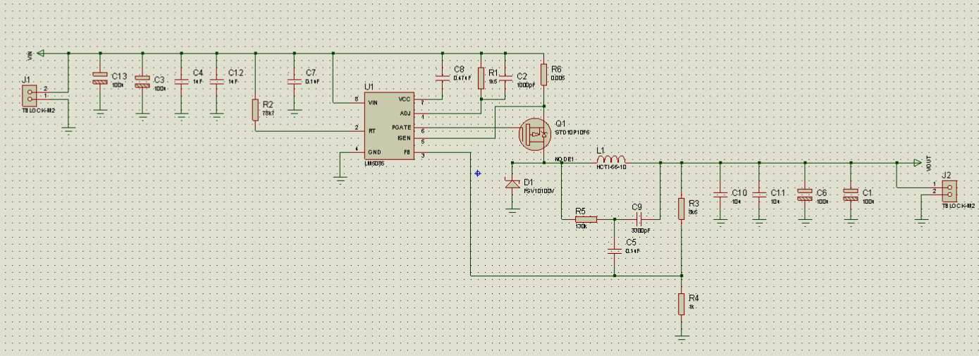
I'm having trouble to get the LM5085 to get an output 12V 10A from a 60V supply.

The design works fine until around 3A, above that point it start to make strange noise and breaks down and burns the FET. Before that, it runs fine at 3A (no heating). I replaced the FET with some big ones for testing, same behavior but the FET survive.

I use a variable resistor load for the tests, nothing special on the output.

It does not seem to be related to the current limiting (The behavior is different when it's in current limiting mode). 

I also tried to increase the inductor to have a higher Isat and higher inductance but does not make much difference. 

Any tip would be very appreciated.

Thanks

  • Damien,

    1. Make sure the layout places the VIN caps close to the FET and create a small current loop. Also make sure there's a small cap very close to the VIN pin of the IC.
    2. Observe the switch node (where D1, FET, and L1 meet). Is this a relatively constant rectangular wave or does it wobble (and does it wobble more at higher loads?).
    3. Check that the layout has proper heat sinking for the FET. The FET should have enough copper to dissipate this heat.
    4. Check to see that the PGATE signal is pulling the PFET gate down enough

    -Sam
  • Hi Sam,

    I did place the cap as close as I could.

    I did some tests with a IRFR9024 and it did seemed to work fine until I soldered the main heat sink, to which point I couldn't reproduce and it behave as described before.

    It does work if there is no load, but as soon as 300mA is drawn the FET heats a lot. and above 1A instantly burns.

    I've checked the waveform and seem to be ok, the gate is pulled around -7V to which the mos should be able to draw 10A.

    There is some wobble on the gate which could be the cause and if that is on the "normal" range or if there is an issue, but I'am not sure what could be the reason.

    One thing is that the LM5085 is relatively far from the FET and the gate has a trace of about 40mm. I tried to add an additional wire to lower the trace resistance but didn't had significant effect.

    Although as it worked for a while (I could draw 4.5 A for a few seconds at a time, as the main FET heat sink pad wasn't soldered) I tend to think this shouldn't be a major issue.

    There  is no major difference on the waveform with and without load.

    The board was "hacked" to add the current limiting using a 4-point sense resistor.

    Yellow is gate, blue is the switch node.

    No Load:

    Load

    Some wobble on the gate

  • Damien,

    I see thermal reliefs on all of your pads but it's hard to see the FET pads 1 and 3 as well as the diode pad 3. Do these also have thermal reliefs?

    -Sam