This thread has been locked.

If you have a related question, please click the "Ask a related question" button in the top right corner. The newly created question will be automatically linked to this question.

UCC27211: UCC27211

Part Number: UCC27211
Other Parts Discussed in Thread: UCC27210, LM5101A, CSD19531Q5A

Hellow .

I am looking the UCC27211 gate driver for our project.

-- Description about project.

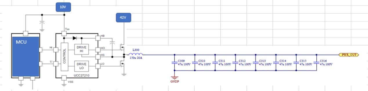
 -  Application : Solar  /   300w Power optimizer   /  DcDc Converter _buck type  PWM duty 50~90% , frequency 40khz  / 

  Below is draft Schematic.


So I have some qustions. I  need your help. 

1. can you recommend "FET" for the hi side and low side ?  I think that  Qg  ,Rds ,Ciss ,Coss ,etc. of FET are very critical point for the stable . 

2.  How to get tecnical support in Korea ?   

Thanks.

Sean Do.

  • Hello Sean Do,
    I am an applications engineer supporting the UCC27211 device and will work to address your questions.
    The schematic did not show up in the previous post, so I can only make general suggestions for MOSFETS.
    TI offers high performance MOSFET's with low gate charge with 100V ratings that should work for the solar application.
    If the application is a non isolated synchronous buck, I would suggest paying attention to the body diode reverse recovery time also. If the application is an isolated bridge converter body diode reverse recovery may not be as important. I would look at the CSD19533 100V MOSFET for faster body diode and CSD19531 for slightly lower Rdson to start.
    For the local support in Korea, if you are working with a distributor contact them and they can provide support or refer to the appropriate local contact. TI support depends on the company you are working.

    Best Regards,
    Richard Herring
  • Hi Richard Herring

    Thanks for the fast reply.

    Here is draft sch.  [ Not UCC27210  , I am using UCC27211  ]

    Can you let me know that if it  has to be additional parts and circuit  with your suggested parts?

    Thanks

    Sean Do.

  • Hello Sean Do,
    Thank you for the schematic.
    Regarding the additional parts. I would suggest adding provisions for a small capacitance on the LI and HI pins to VSS placed very close to the UCC27210 IC. Also I would suggest adding a series gate resistor, or resistor and parallel diode between the driver HO and LO outputs to the MOSFET gate terminal. You can start with a resistance of 2.2 to 4.7 Ohms and evaluate in the testing. You will want the ability to control the MOSFET turn on transition in order to minimize the switch node turn on voltage spike and stay within the MOSFET VDS voltage rating.

    Please confirm on the thread if this addresses your questions.
  • Hi Richard Herring

    I need more detail description about below list.
    1. Reason why series gate resistor and parallel diode need to use to this SCH . What it is role with this circuit ?
    2. How to decide value bootstrap cap ?

    Can you let me know how to get CSD19533 and CSD19531 by ti sample services system?

    BR.
    Sean Do.
  • Hello Sean Do,

    For the questions 1 above regarding the gate resistor and parallel diode. This is a recommendation I make as good practice on a new design to accommodate the ability to optimize the performance of the converter. The gate resistor, and ability to adjust, will provide the ability to slow down the switching of the FET's if desired for several possible reasons. One is to reduce the dV/dt on the switch node to reduce the emissions to meet EMI requirements. Another in a buck converter as you show is to reduce the switch node turn on spike during the turn on of the high side power MOSFET.

    The parallel diode allows for having a faster turn off VGS than turn on. After testing, you may determine these components are not necessary and can just install a 0 Ohm resistor. I would at least recommend a gate resistor on the schematic to allow adjustment in the design.

    For the boot strap capacitor I would recommend reviewing Section 9.2.2 in the LM5101A datasheet which is a similar 100V half bridge driver. The link is:

    http://www.ti.com/lit/ds/snosaw2q/snosaw2q.pdf

    The datasheet also provides guidance for selecting the gate drive resistors.

    For the samples if you go to the product page for the CSD19531Q5A and the order now tab, there is a request sample tab where you can get samples for no cost. If you want more than one sample click the Edit button. See the link below:

    http://www.ti.com/product/CSD19531Q5A/samplebuy

     Please confirm if this answers your questions.

    Best Regards,

    Richard Herring


  • Hi Richard Herring

    Your answers are very helpful for me .  Thanks for your support and effoert.

    I'm going to do start design and decied circuit with your comments.

    But I want to centect you or TI tecnical support system if I  get another issue or somting problems.

    BR

    Sean Do.  

  • Hi Sean,

    You bet! If you have any further questions, please let us know here on e2e, and we will do out best to help you!

    If you can mark Richard's Answer as Verified, it would help us a lot.