This thread has been locked.

If you have a related question, please click the "Ask a related question" button in the top right corner. The newly created question will be automatically linked to this question.

DCV011515D: DCV011515DP-U

Part Number: DCV011515D
Other Parts Discussed in Thread: DCV010505, OPA189

Currently I am using DCV011515DP-U in my board for powering opamp. There are two DC-DC converter DCV011515DP-U per board. The specifications are mentioned below:-

1) Input voltage to DC-DC converter = 15VDC (fix and same to both DC-DC converter).

2) Load on each output voltage (+15V, -15V) of both DC-DC converter = 6mA (max).

3) SYNCIN and SYNCOUT pins of both DC-DC converters are kept floating in our board.

The issue with the DC-DC converter is that in every board one of the DC-DC converter is not working (mean to say not developing specified output voltage).

The same is issue is observed with 3 fabricated board.

Kindly provide proper suggestions for the same.

  • Hi Vedang:

    In order to better assist you on the DCV011515D  ,send  the following information sent directly  to me at tguerin@ti.com .

    Question :

    What are the op- amps driving and what is their +-- Vcc range ? What the Op- amp output circuit ? What is the maximum secondary voltage on this output circuit

    A complete schematic of both DCV010505 of the  application, including all input and output ceramic  capacitors , µF capacitance  and location of these capacitors.

    A layout diagram and capacitor component connections.

    Identify which DCV011515D is functioning and which one is not functioning.

    2.Measure input voltage directly at the input pins, pin 1( Vin+) and pin2( Vin(-),on each DCP011515D

    3. Measure  and record the output sync. Pin , pin 8 voltage on each DCV011515De. This may be AC/DC   AC switching Pulses.

    Tom

    Tom

  • Dear Tom Guerin,

    I have mailed you the schematics. Kindly don't share the schematics.

    Regarding the opamp, we have used OPA189 and the output voltage range is ( 0 – 10VDC).

    The capacitors selected are as per the application information guide of Texas Instruments’ datasheet.

    Currently we have fabricated 3 cards and following are the issues observed with three cards.

    Card 1 = U5 not functioning.

    Card 2 = U3 not functioning.

    Card 3 = U5 not functioning.

    Exercises performed on the faulty boards:-

    1) I have also checked by lifting the pins of non-functioning DC-DC converter so as to check loading on the same. But to our surprise the DC-DC converter still didn’t developed the required specified output voltage upon +15VDC input voltage.

    The output voltage developed by the DC-DC converter upon specified +15VDC input voltage is shown below:-

    CARD 1 U5 = +9.6V, -9.9V (at no load).

    CARD 2 U3 = +6.7V, -6.5V (at no load).

    CARD 3 U5 = +14V, 13.7V (at no load).

    2) Then I thought the layout might be an issue with the DC-DC converter so I took out the faulty DC-DC converter from the board mounted it on the general purpose PCB, but still it didn’t developed the required specified output voltage upon +15VDC input voltage.

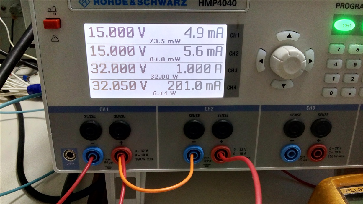
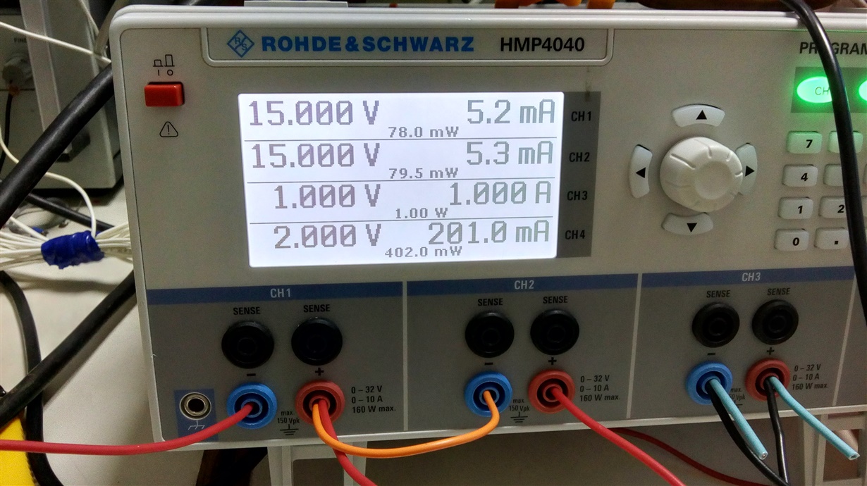
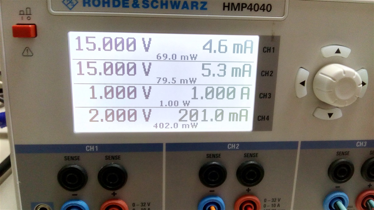
    3) The sections which were powered by the DC-DC converter were also checked for its functionality but the loading didn’t seem to be an issue. I am sending the screenshots of the load currents of the sections of the boards which are powered by the not functioning DC-DC converter. In the photos channel 1 and channel 2 were used for powering up the PCB.

    4) The SYNCIN & SYNCOUT pins of the DC-DC converter were kept floating in our application. However I tried to connect the SYNCIN pin of both the DC-DC converter on the fabricated PCB, but still the specified output voltage was not developed in one of the DC-DC converter.

    Kindly suggest some solution for the same because this circuit was tested on general purpose PCB by soldering the required components and it worked fine. Now we are facing issues in every fabricated PCB.

    Hoping for quick reply from your side.